LIBRARY
Three-Terminal Common-Mode EMI Model for EMI Generation, Propagation, and Mitigation in a Full-SiC Three-Phase UPS Module

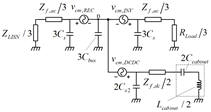
The UPS under study is composed of three power conversion stages: a rectifier, an inverter for ac-ac conversion, and an active battery charger with a battery rack as energy storage. The complete UPS model for EMI is derived as shown in Fig. 1. The common-mode voltage (CMV) of each power conversion stage (vcm,REC, vcm,INV, vcm,DCDC) is defined as the average terminal output voltage referring to the mid-point of the dc-link. The model also includes the impedance of the LISN (ZLISN), the impedance of the resistive loads (RLOAD), the impedance of the switching harmonic filters (Zf,ac, Af,dc), as well as the parasitic components (Cs, Cs2, Cbus, Ccabinet, and Lcabinet).
The model provides insight into how CM noise will change when the dc-dc converter operates. When it operates, the CM noise generated by the rectifier, inverter, and dc-dc converter propagates through the battery cabinet to the ground. Within this path, the parasitic components of the battery cabinet are present and create resonances with the dc inductor. Together with additional CMV generation, these resonances deteriorate the CM noise profile.
Based on the developed model, an EMI mitigation strategy for UPS is investigated with the focus on topology and PWM scheme selection. The three-level topology with LMZVM is selected for the rectifier and inverter implementation as it has lower CM emission and provides a good control of neutral point voltage. The three- level bi-directional dc-dc converter with a synchronized switching sequence is selected for the dc-dc stage as it has eliminated CM emission in ideal conditions, and it provides good manufacturability by sharing the same phase-leg with the ac-ac stage.
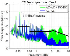
A 20 kW full SiC UPS has been built to verify the impact of dc-dc converter operation and the mitigation strategy. All the power conversion stages utilize 1.2 kV 40 A full-SiC NPC modules and have a switching frequency of 60 kHz. The CM noise spectra for two different modes of operation are compared, as shown in Fig. 2. With the dc-dc converter operation, the CM harmonic component at 180 kHz is increased by 6.8 dB. This is critical for the EMI filter design. Over 12 MHz, the CM noise has been increased by a maximum of 12.5 dB. Over 230 MHz, a high increase in the CM noise was observed, which does not exist in the double-conversion mode.


