


LIBRARY
Low Loss Integrated Inductor and Transformer Structure and Application in Regulated LLC Converter for 48V Bus Converter
Year: 2020 | Author: Ahmed Nabih | Paper: T3.10
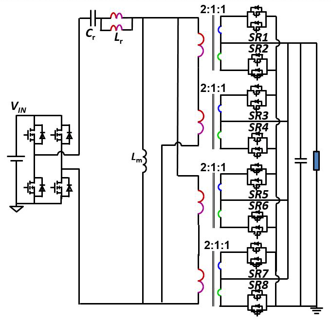
Fig. 1. Single stage LLC DC/DC converter with matrix transformer
In this work, a single stage LLC converter with integrated mag- netics is proposed for 48 V/12 V-1 kW bus converters that can provide both regulation and isolation. The current practice for dc-dc-bus converters is to operate at low switching frequencies, 100-200 KHz, with power density below 400 W/in3. For higher power density, this converter will operate at a 10-times higher frequency than indus- try practice. The LLC converter is most suitable for high-frequency operation due to its soft switching properties for all devices so that higher efficiency and power density can be realized. For high output current and low voltage dc-dc converters, the matrix converter has proven to be a perfect candidate as it distributes the secondary cur- rent among different outputs to reduce the total conduction loss.br> In this work, two matrix transformers, each with two transformer outputs, is used to deliver a 1 kW output power. The two transformers are connected in parallel from both primary and secondary windings as shown in Fig. 1; the primary windings are arranged in a way to integrate the parallel transformers with one core structure.
To achieve output voltage regulation, the resonant inductor needs to be designed to a specific value to have the required regulation capabilities. A novel magnetic structure is proposed where the transformer primary windings are extended with the addition of a magnetic core to achieve a controllable leakage inductance to achieve the regulation capabilities. The shared winding will result in lower losses of the resonant inductor. The proposed PCB winding arrange- ment is shown in Fig. 2. A prototype has been developed for the pro- posed converter, achieving a power density of 800 W/in3 with an es- timated efficiency > 97% higher than all available industry practices.
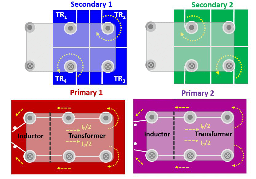
Fig. 2. Integrate matrix transformer and inductor PCB winding arrangements
