


LIBRARY
Design Analysis for Current-transformer Based High-frequency Auxiliary Power Supply for SiC-based Medium Voltage Converter Systems
Year: 2020 | Author: Ning Yan | Paper: T3.15
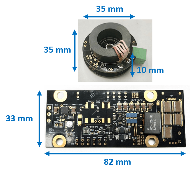
Fig. 1. Designed auxiliary power supply with multi-channel for medium-voltage application.
For these purposes, a GaN-based, high-density power supply solution is designed, as shown in Fig. 1. This power supply has a constant output current on the primary side, so it is able to supply multiple loads simultaneously regardless of load location. Additionally,the designed power supply is able to achieve 1) a total power of 120 W for each sending side and 20 W for each receiving side; 2) soft switching (ZVS) with an arbitrary number of loads with parasitic inductance in consideration; 3) circuit failure immunity; and 4) an ultra-small coupling capacitor.
For the designed auxiliary power supply, operating stably in a medium-voltage system is the main goal to achieve. Thus, a 6 kV buck test is conducted. In the buck test, the designed power supply is used to power the gate driver for 10 kV SiC MOSFETs. As shown in Fig. 2, the designed power supply has stable output in a strong dv/ dt system. Therefore, the designed power supply has stable electrical performance and is ready to be used in a medium-voltage system.
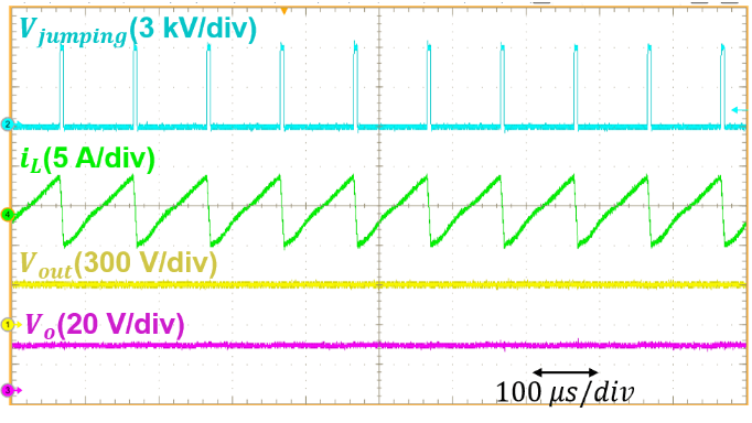
Fig. 2. Experiment verification for the design auxiliary power supply in 6 kV continuous test.
