


LIBRARY
Design-Oriented Equivalent Circuit Model for Resonant Converters
Year: 2020 | Author: Yi-Hsun Hsieh | Paper: T3.5
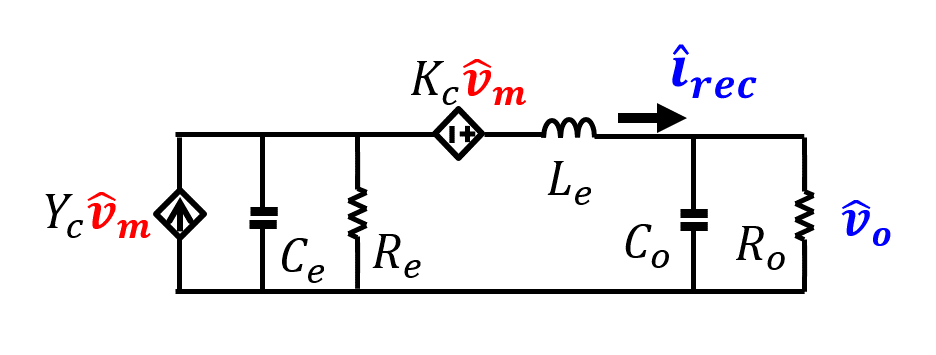
Fig. 1. Proposed small-signal equivalent circuit model for SRC and LLC resonant converters.
Yang developed a complicated equivalent circuit model based on the harmonic balance principle and demonstrated on the series resonant converter (SRC). His work was later extended to an LLC converter by Chang. However, their models were based on the as- sumption that the resonant tank behaves as a good band-pass filter, which is applicable at best to SRC at high Q, but not for LLC type of resonant converters. In fact, most of the poles predicted are located beyond the switching frequency (FS). Consequently, some simplified models are proposed. However, those models are based on funda-mental approximation, and the simplification processes further sacrifice accuracy.
The recent modeling breakthrough is based on the extended describing function method when all harmonics are taken into consideration. These models are demonstrated to be accurate at all frequencies and thus set a solid stage for a further simplification when the frequency range of interest is below FS, as in most applications. Based on this modeling, a design-oriented equivalent circuit model is proposed, as shown in Fig. 1. With its simple form, the proposed model provides strong physical insights into the dynamics of resonant converters and leads to strategies for optimal controller and power stage designs. For example, the nature of the control-to- output transfer function shown in Fig. 2 can be well-explained with the proposed model. The Le in Fig. 1 represents the energy stored in the resonant tank and forms the beat-frequency double-pole with Ce. Re is the Thevenin resistance of the resonant tank. Under typical operation as FS around the resonant frequency, the LLC converter behaves as a voltage source and therefore Re is very small. In this condition, there is a strong double-pole formed by Le and C0 so a Type &SHcy compensator is needed for a high-bandwidth design. Moreover, the high-frequency single pole and right-half-plane zero contribute to an additional phase delay. Their frequencies are shown to be a function of the intrinsic impedance of the resonant tank. This insight becomes a strong guideline of power stage design in achieving higher performance.
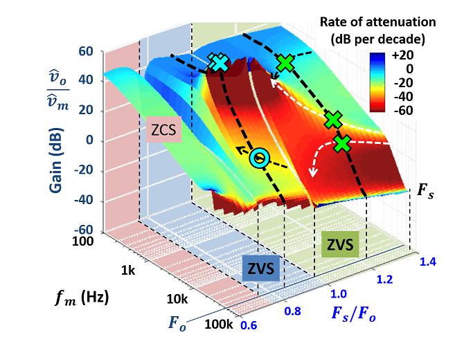
Fig. 2. Control-to-output transfer function for LLC resonant converter.
