


LIBRARY
Design of IPT Transformer under Space Constraint
Year: 2020 | Author: Bo Li | Paper: T3.7
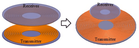
Fig. 1. Concept of reducing receiver size.
Coil inductances and resistances in conventional transformers are designed to minimize transformer loss while achieving desired system efficiency. This is then followed by mechanical and magnetic realizations. The main objective is to minimize receiver coil size while satisfying desired system efficiency. The basic idea for optimization is to increase the transmitter size to enable a smaller receiver size, which is shown in Fig. 1.
The value of mutual inductance needs to be at a certain value in IPT systems with series-series compensation for desired power level and fixed input and output voltage. Appropriate coil size is then designed to achieve the desired mutual inductance. Coil current increases with the power level, which will need a larger wire gauge to have reasonable current density in the wire for thermal considerations so that coil size becomes larger at higher power levels. In this work, smaller receiver coil size is enabled by increasing the number of turns at a larger transmitter coil to keep the mutual inductance at a certain range.
In the optimization, the receiver loss and transformer loss were calculated by sweeping for fixed receiver coil size and variable transmitter coil size. For each transmitter coil size, receiver loss and total transformer loss is calculated by the number of sweeping and the turns pitch at the transmitter and receiver. Pareto Front is then utilized to show the trade-off between receiver loss and total trans- former loss. Fig. 2 shows such Pareto Fronts for different transmitter sizes. For a specific receiver size, maximal allowed loss can be determined with the thermal requirement under specific cooling condition. An appropriate transmitter size that satisfies both the trans- former efficiency and the receiver loss limit can be finally selected. An example of the design point is shown in Fig. 2, with receiver loss limited within 50 W and transformer loss limited below 200 W.
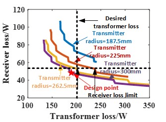
Fig. 2 Trade-off between receiver loss and transformer loss for different transmitter size.
