LIBRARY
Analysis of STATCOM Small-Signal Impedance in the Synchronous D-Q Frame

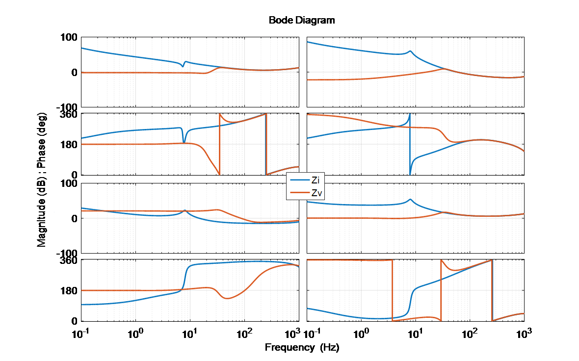
From the model proposed, the following conclusions are extracted. First, because of the inherent operating conditions of a STATCOM, the stability assessment directly from the d-q frame impedances is very difficultas opposed to unity power factor rectifiers and inverters, for which a multivariable stability theorem using the return-ratio matrix product of the upstream and downstream impedances at a given ac interface must be used (for example, the GNC). Second, the ac voltage loop of the STATCOM is found to be the strongest contributor to its terminal impedance and consequently to its small-signal stability conditions as shown in Fig. 1. This loop was shown to effectively mask the PLL dynamics, especially for proper system parameters of transmission grids, previously shown to be critical in grid-tied power converters. Third, and very importantly, the STATCOM impedance is shown to be able to behave both as a CPL rectifier and as a grid-tied inverter injecting power into the grid, from a dynamic standpoint, featuring a negative incremental input-impedance in its Zdd or Zqq impedance elements respectively, as a function of its reactive power injection mode (capacitive or inductive), and as a function of the relative phase between the d-q frame in question and the voltage at the PCC. These are all unique impedance characteristics that make the stability analysis in the presence of STATCOMs more involved than other unity power factor converters. Fourth, alternative control is also modeled, which revealed the impacts on impedance shaping to mitigate the new instability pattern. A 2-STATCOM study case is simulated that validated the above conclusions. Lastly, the model is verified experimentally using an IMU to measure the input-impedance of a 10-kVAR STATCOM prototype, which is shown to match up very well with the impedance obtained using the developed model.


