LIBRARY
A Two-Stage Rail Grade DC/DC Converter Based on GaN Device

In railway applications, isolated power supplies are required to transform the floating battery voltage to a constant output for different loads. In order to find a cost-effective solution, the modularized design method can be applied here. The whole power supply is built with several identical dc-dc brick modules, and each module should be able to communicate with a central controller. Thus, it requires a high-efficiency, high-power-density dc-dc module with digital controllers. However, the existing commercial modules use analog controllers and do not support external communication. Meanwhile, with Si MOSFET, they can only achieve relatively low peak efficiency and low power density.
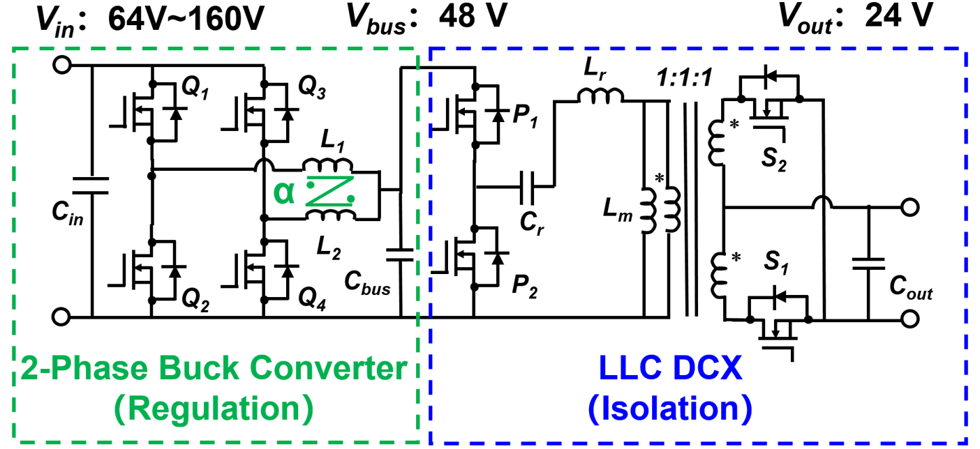
The proposed module in this paper, as shown in Fig. 1, uses a two-phase critical mode (CRM) buck converter to offer a regulated 48-V bus voltage, and then an unregulated LLC converter (DCX) serves for 48 V/24 V conversion. This paper focuses on the design and control of the proposed converter. Considering the maximum input voltage and output voltage, the GaN devices are compared and selected for the buck converter and the LLC DCX, respectively. The CRM operation under a negative coupled inductor is discussed. The ZVS range is discussed and ZVS extension is developed to cover the wide input range. Finally, all the mentioned control functions are implemented through a small and low-cost 60 MHz MCU.
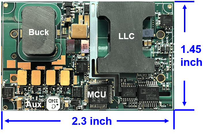
Fig. 2 shows the prototype system, which includes the main circuits, the planar magnetics, the MCU, and the auxiliary power supply. The standalone prototype converter has a measured peak efficiency of 95.1% with a power density of 130 W/in3.


