


LIBRARY
A Distributed Hierarchical Digital Control System for Medium-Voltage Modular Converters Enabling Peak Current Mode Control for Parallel Operation
Year: 2020 | Author: Qian Li | Paper: T4.6
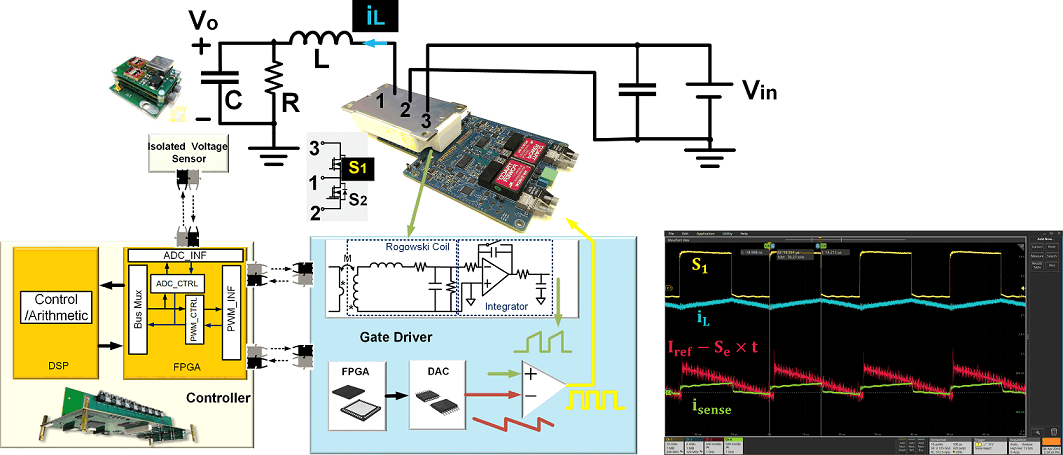
Fig. 1. Hierarchical digital controller of modular converter operating PCM.
As shown in Fig. 1, for each converter in parallel operation, current loop reference is generated from the controller based on output voltage sensing information and is transmitted digitally through an optical cable to the gate driver, which further increases the noise immunity of the modular converter. After deducting external ramp values in the local FPGA for stability consideration, the current reference is sent to the digital-to-analog converter (DAC), and the DAC finally generates the analog signal to be compared with the sensed top switch current from the Rogowski coil sensor directly. In this way, not only is the modulation delay for the current loop minimized, it also helps to eliminate the need for extra current sensors in the modular converter and thus demonstrates the potential for a more compact design. The schematic diagram for the medium-voltage modular converter in parallel operation is shown in Fig. 2. The output inductor currents, labeled as iL1 and iL2, are captured. It can be seen from the experimental waveforms that good load current sharing between the paralleled modular converters is achieved.
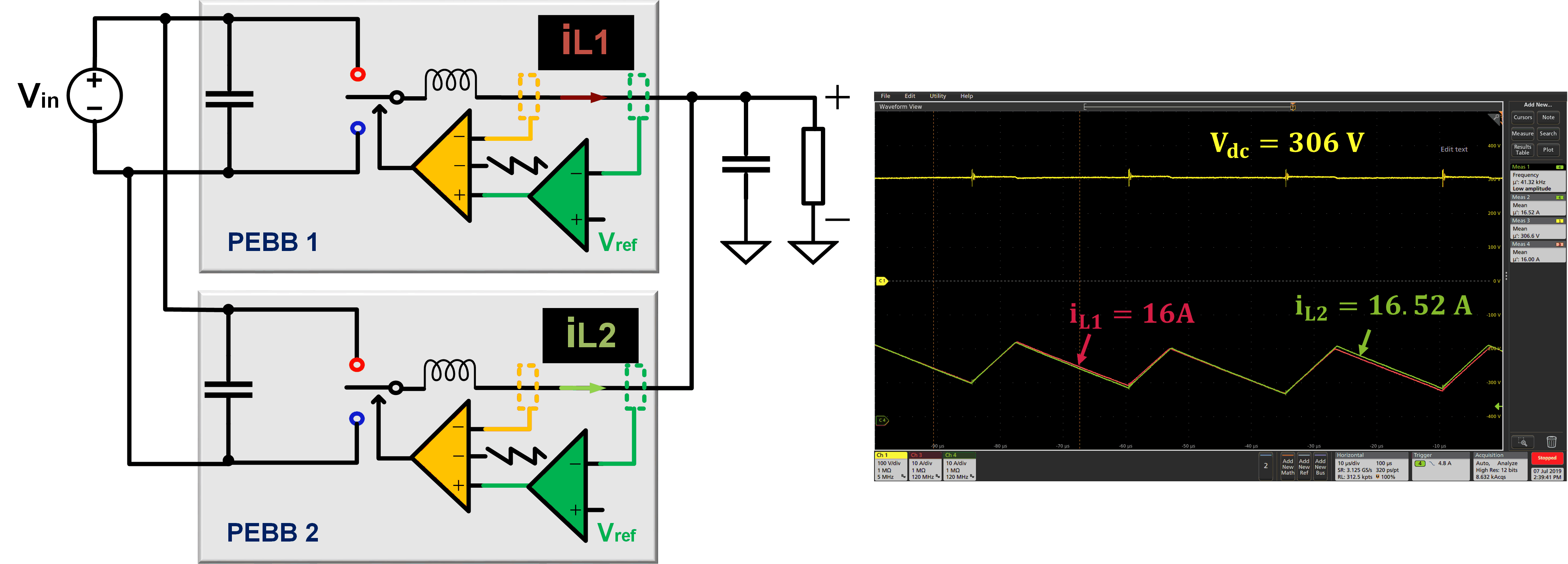
Fig. 2. Current sharing performance of modular converter in parallel operation with PCM.
