


LIBRARY
SST Based 400kW Fast Charger
Year: 2020 | Author: Chunyang Zhao | Paper: T5.28
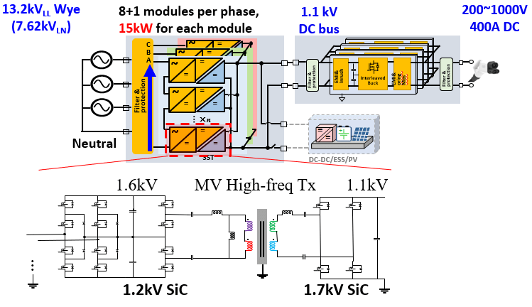
Fig. 1. System structure and one submodule
Fig. 1 shows the whole fast-charger system with 13.2 kV medi- um-voltage input and 1.1 kV output voltage, and a three-level CLLC resonant converter circuit of cascaded submodules. This resonant converter is a dc-dc conversion component respectively connected in SST. It converts 15 kW from ac-dc PFC output 1.6 kV dc to a 1.1 kV dc dc-bus and then to a fast-charger module.
Devices for both the primary side and secondary side are se- lected based on device loss evaluation. Magnetizing inductance Lm and deadtime td are selected based on the requirement of zero voltage switching (ZVS). Transformer core material candidates are evaluated using the specialized core-loss measurement techniques developed at CPES, and the core material is selected based on the switching frequency. Litz wire is also selected based on the switching frequency. Considering the insulation requirement, the insulation materials and winding structures are evaluated and selected to minimize the transformer volume. The transformer loss is then calculated using the magnetic core loss model and litz wire winding loss model devel- oped in CPES. Finally, all the transformer design parameters, such as number of turns, core loss density, and switching frequency, are optimized based on the trade-off between the volume and converter total loss, as well as winding loss and core loss. A prototype is built according to the optimized design, as shown in Fig. 2.
The CLLC resonant converter operation principles are analyzed and verified through experimental result. The efficiency of one sub- module is tested and compared to the design result. Additionally, the insulation capability of the medium-voltage, high-frequency solid- state transformer is also studied and discussed in the paper, especially its performance on the partial discharge test.
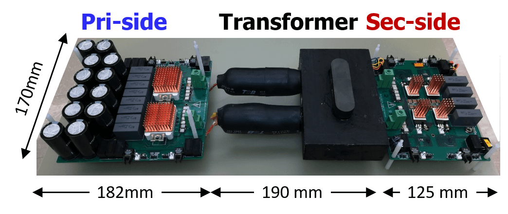
Fig. 2. Three-level CLLC resonant converter prototype
