


LIBRARY
Development of Impedance Measurement Unit for 1 kV DC and 800 V AC Systems
Year: 2020 | Author: Sizhan Zhou | Paper: T5.29
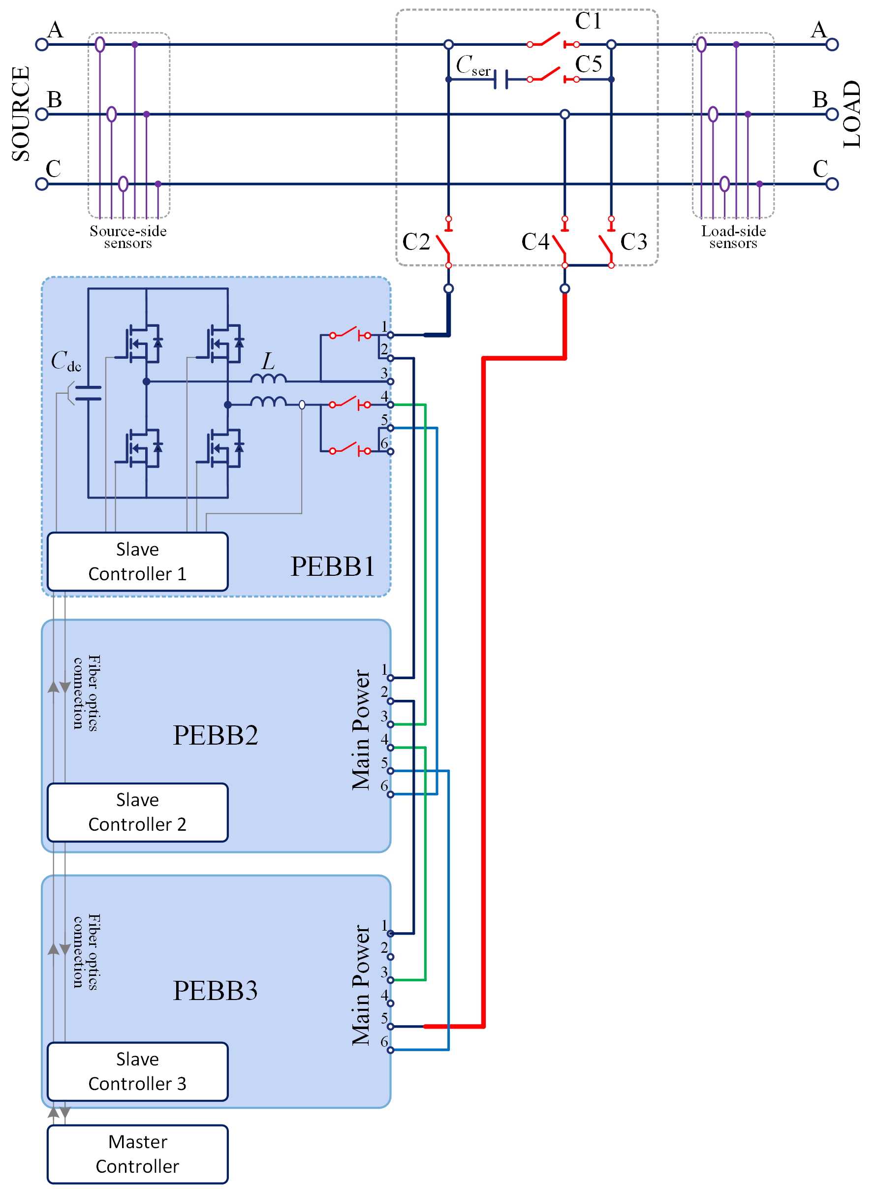
Fig. 1. Power stage of the impedance measurement setup.
Fig. 1 shows the IMU power-stage topology capable of characterizing impedances of 1 kV dc and 800 V ac networks in the frequency range of 10 Hz1 kHz. The power-stage comprises three power electronics building blocks (PEBBs) and a switching network. Each PEBB is an H-bridge converter with maximum 200 A current capability and 1 kV-rated dc-side voltage and is built using 1.7-kV SiC MOSFET. By configuring the state of the switching network, the IMU can work in shunt current and series voltage injection mode, both of which are needed to accurately measure subsystem impedances. In shunt mode, PEBBs are configured as a five-level cascaded H-bridge converter with 3 kV dc voltage in total to inject current perturbation for source impedance characterization. In se- ries mode, PEBBs are configured as a parallel-interleaved converter to inject voltage perturbation for load impedance characterization, and controlled to equally share the system current. The IMU control is implemented based on the distributed control scheme in which PWM signals of each PEBB are generated by a local slave controller, and a master controller connects with all slave controllers through a ring-type communication network to obtain circuit states and realize high-level control. The IMU is designed and implemented with a modular and scalable structure and consequently can be extended to medium voltage level.
A hardware prototype has been bulit as shown in Fig. 2 and tested at the rated working condition to validate its impedance iditi- fication capability.
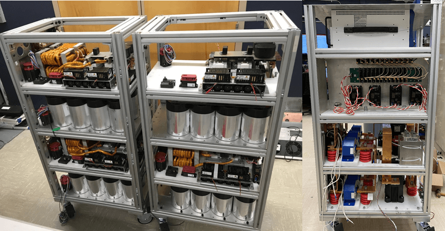
Fig. 2. IMU hardware prototype.
