Fig. 1. Double-enclosure insulation system of a self-designed medium voltage modular converter equipped with 10 kV
SiC MOSFET.
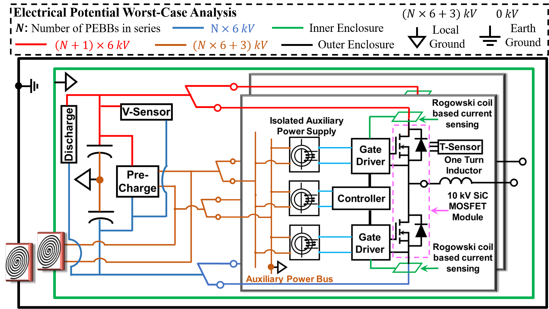
During the construction of a 6 kV Power Electronics Building Block (PEBB 6000), reliable and compact insulation design and realization is one of the important considerations. A good insulation system that can achieve PD free during normal operation not only helps to achieve an expected insulation lifetime and enhances the electric performance of the converter system, but also avoids any cascaded failure that may be initialized by some significant discharges. In Modular Multilevel Converter (MMC) topology, as we plan to stack four PEBBs up and thus hold a 24 kV system voltage, a widely used double-enclosure insulation strategy is applied for each of the PEBB units, as shown in Fig. 1. By connecting the inner enclosure with the local ground of each PEBB unit, there is only up to a 6 kV differential voltage between any adjacent components in the same PEBB. The remaining part of the system level voltage (up to 27 kV) is then pushed into the area between the inner and outer enclosures. Therefore, the insulation design can be decoupled into two levels (individual PEBB and system integration level), which leads to a more modular, flexible, and compact PEBB architecture. However, the area between the two enclosures needs some careful analysis and insulation design due to the 27 kV. Focusing on the area between the two enclosures, two critical regions can be identified as shown in Fig. 2. As there are several uncontrolled sharp edges and corners in the heatsink on the bottom and along the small ICs of the PCBs on top, the insulation distance in air for these two regions must be very large (around 100 mm) in order to avoid discharges under 27 kV. Thus, the active Electric Field (E-field) management method, basically speaking the E-field-shielding technology, must be applied, in order to make the E-field distribution uniform and shrink the required minimum insulation distance in air. In this paper, the design methodology of shielding plate in MV power converters is proposed. Then fabrication of shielding plate and its experimental verification are demonstrated.
With proper E-field shielding, the minimum insulation distance can be 30 mm, which leads to more than 50 % volume reduction.
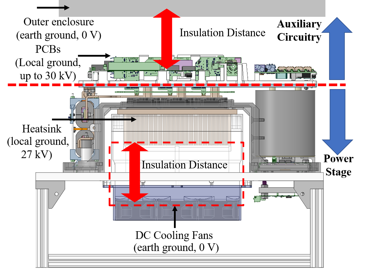
Fig. 2. Critical regions between two enclosures for insulation design.


