LIBRARY
Piezoelectric Transformer-Based High Step-Down Voltage-Ratio DC-DC Converter

By contract, the piezoelectric transformer (PT), an electromechanical coupled transformer, whose equivalent circuit can be represented by the integration of a resonant tank and an ideal transformer, may provide an alternative solution. Among many types of PTs, the high-voltage Rosen- type PT features natural mechanisms for high- voltage insulation, high-transform ratio in a compact planar form, no coil winding, and no EMI source, providing an alternative solution for dc bus-fed, high step-down voltage-ratio auxiliary power supplies in medium- or high-voltage systems.
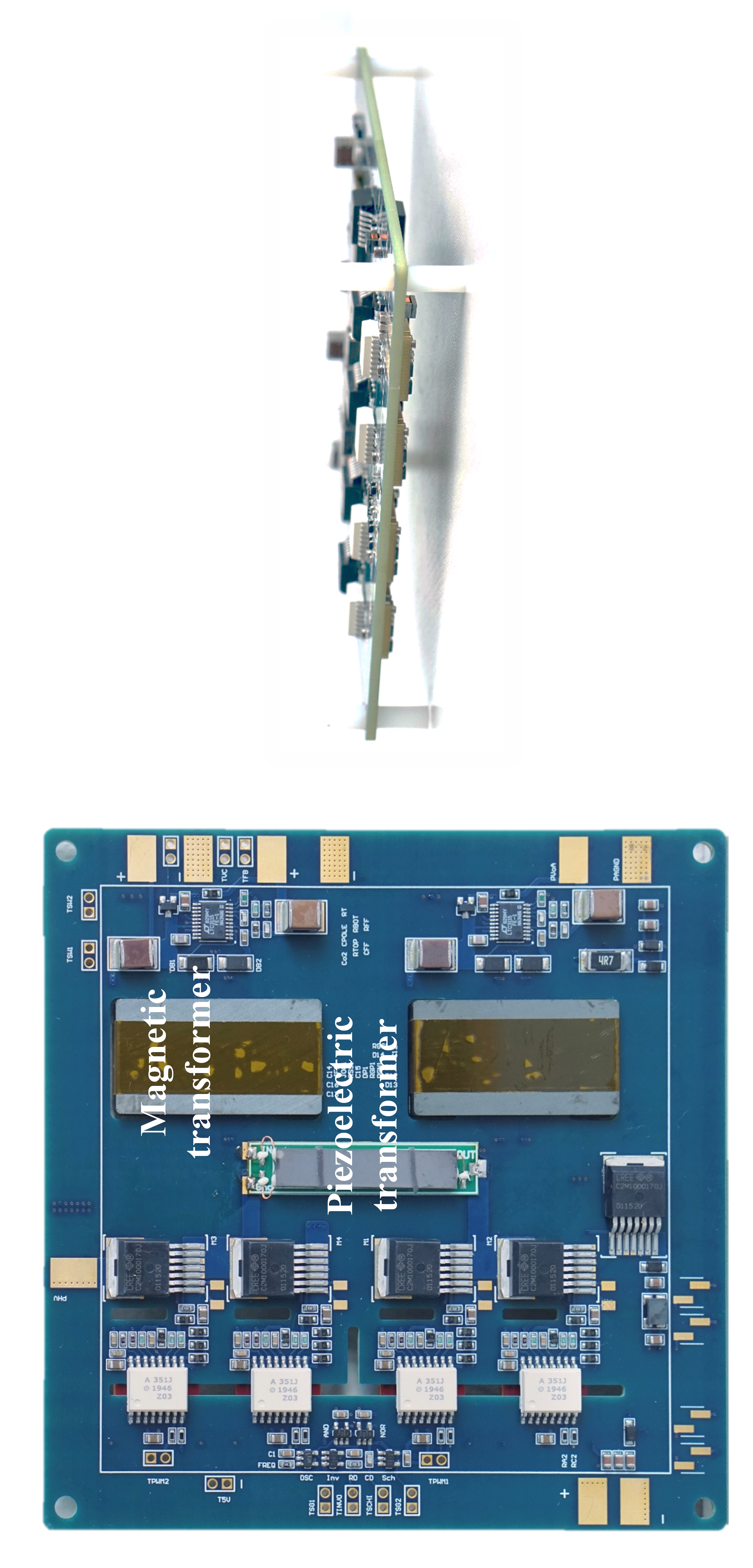
Fig. 1 presents the topology of the proposed converter. A full bridge is used to generate the ac voltage for the PT and to provide wider input regulation range compared to the half bridge. Since the PT steps down the voltage, a 1:1 planar magnetic transformer is used afterwards to provide the isolation since current commercial high-voltage PT is non-isolated, where the magnetizing inductance is utilized to improve the efficiency as well as provide load- independent voltage gain. A regulated buck-boost ac-dc stage is used to provide line-regulated output voltage. The control loop sits at the low-voltage side without crossing the high-voltage barrier.


