LIBRARY
High-Frequency Transformer Design with Medium-Voltage Insulation for Solid-State Transformer(SST)

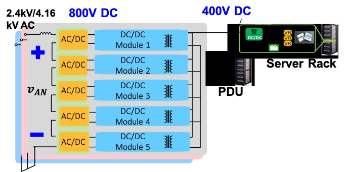
In the proposed system, medium-voltage SST is used as the distribution voltage in the data center to convert medium- voltage ac directly to 400V dc inside each server hall, as shown in Fig. 1. This system can eliminate line frequency bulky transformer, reduce front-end conduction cable costs, and save conduction loss. Each system block consists of ac-dc H-bridge converters together with high-frequency isolated dc/dc converters. In total, five cascaded submodules are employed to convert 4160 VAC directly into 400V dc. The inputs of ac-dc H-bridges are in series and the outputs of the dc-dc stages are connected in parallel.
In this work, a high-frequency, high-efficiency isolated CLLC resonant converter is proposed for a next generation dc data center. The medium-voltage high-frequency transformer is the most crucial component in terms of insulation and power density. A novel UU core with sectionalized winding structure is chosen to enhance insulation capability, restrict leakage inductance, and reduce magnetic loss at the same time. Transformer insulation parameters are calculated based on the IEEE Std. C57.12.01 requirements. An additional conductive shielding layer is applied to restrain the electric field inside the insulationand ensure no electric field in air. A stress grading layer is utilized at termination to spread out equal potential line and thus reduces the E-field around termination. The winding arrangement is optimized based on the smallest insulation volume.
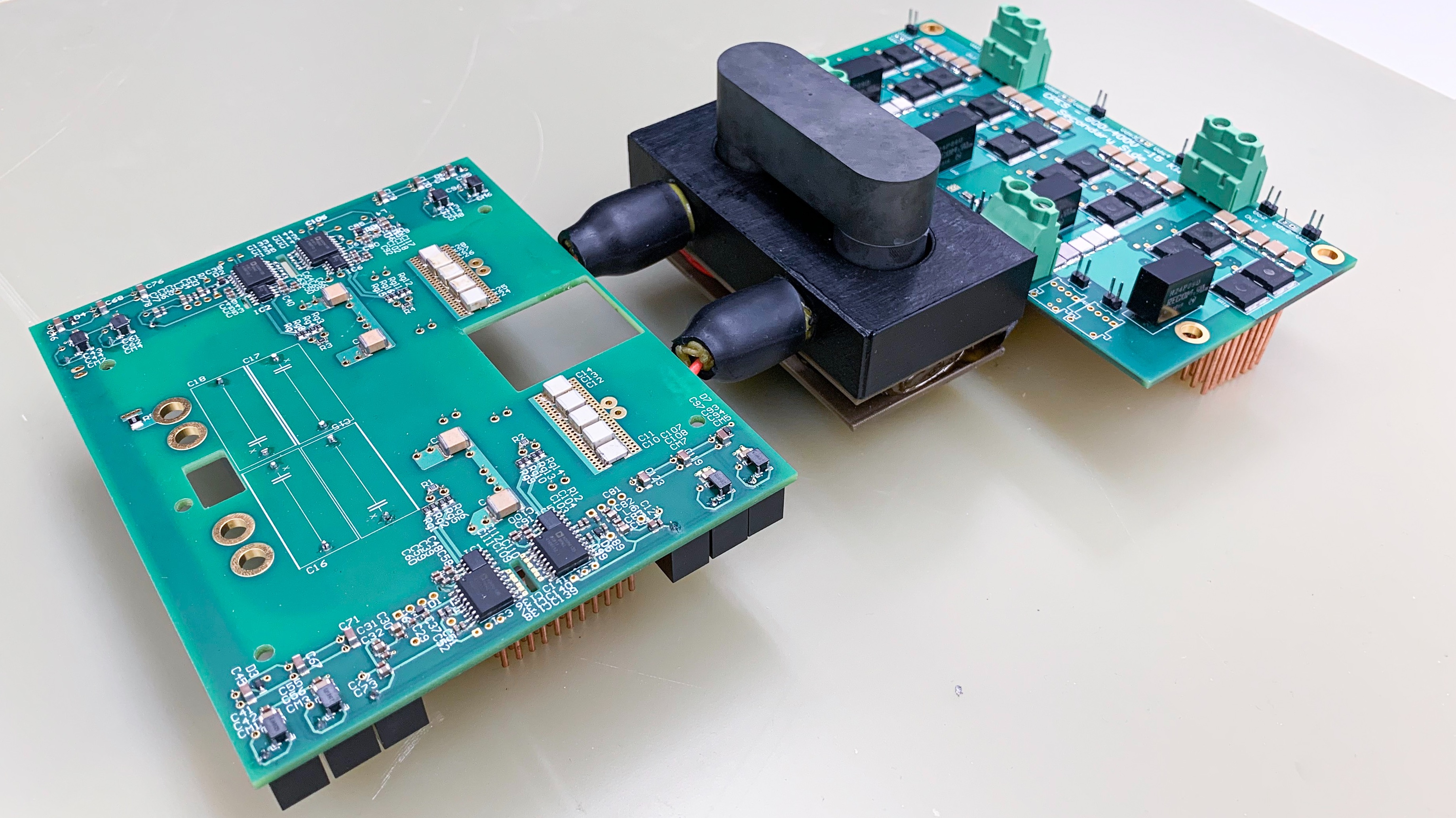
The transformer turns number is determined based on the transformer loss volume trade-off and core loss winding loss trade-off. Different working frequency and different core loss density impact on transformer design is also analyzed based on a similar method. 200 kHz is found to be the best working frequency for ML27D material from Hitachi in this application. A 15 kW/200 kHz converter prototype is developed shown in Fig. 2. Experiment results are also presented with 98.7 % peak efficiency and 61 W/in3 power density.


