


LIBRARY
Coupled Inductor Design for Multi-phase PFC Converter
Year: 2021 | Author: Shuo Wang | Paper: S1.1
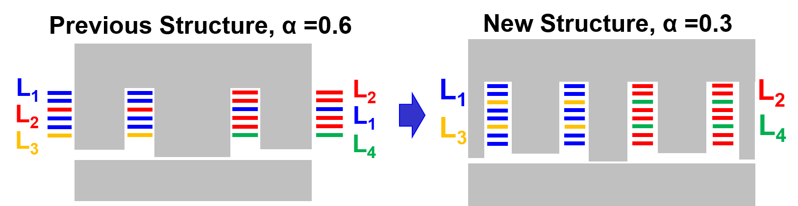
Fig. 1. Proposed PCB winding coupled inductor with PQ core structure.
This research focuses on the design of PCB winding based coupled inductor for multi-phase critical mode (CRM) PFC converter. First, the coupling coefficient is optimized by a trade-off of magnetic flux dc bias and switching frequency range. A higher coupling coefficient leads to a higher dc bias in the outer leg, which results in an increased core loss if an EI core structure is considered. As a contradictory, the coupling coefficient should not be too small in order to avoid a large switching frequency range for CRM PFC converter. A coupling coefficient α=0.3 is selected based on minimizing the dc bias and switching frequency range in outer legs.
Second, improving common mode (CM) EMI noise reduction by balance technique is another highlight. A new PCB winding structure is proposed as shown in Fig. 1. CM noise is expected to be uniformly reduced in the frequency range of 150 kHz to 30 MHz.
Third, an improved coupled inductor design process is presented. The finite element analysis (FEA) based Equivalent Elliptical Loop (EEL) model is employed for core loss calculation. Trade-offs of inductor loss and footprint are performed.
A positive coupled inductor for a 6.8 kW electric vehicle (EV) on-board charger is designed as an example. Fig. 2 shows the loss breakdown of the coupled inductor. The PFC converter is expected to have a peak efficiency over 98% and a power density of 2.7 kW/L. At the same time, CM noise is expected to be uniformly reduced with the proposed integrated coupled inductor.
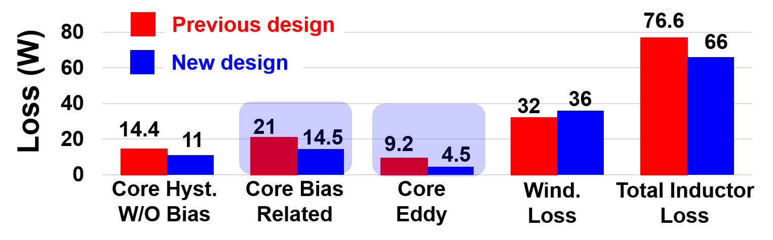
Fig. 2. PCB winding coupled inductor loss breakdown.
