LIBRARY
A Distributed Communication and Control System for Modular Power Converters with Sub-ns Synchronization Accuracy

A synchronization diagram is shown in Fig. 1 based on the WR protocol. Considering a master node and a slave node connected in a bidirectional optical fiber link, the synchronization logic is implemented in each node for the timestamping of t1, t2, t3, and t4. The phase detector in the master node measures the phase difference between master reference clock and recovered clock, phaseM. With phaseM embedded in the packet and received by the slave node, the slave node adjusts the frequency of a voltage- controlled crystal oscillator (VCXO) within the closed- loop PLL, and generates a local clock synchronized with the master reference clock. The closed-loop PLL mainly consists of software-based phase detector and PI controller, and hardware chips including DAC, VCXO, and clock multiplier.
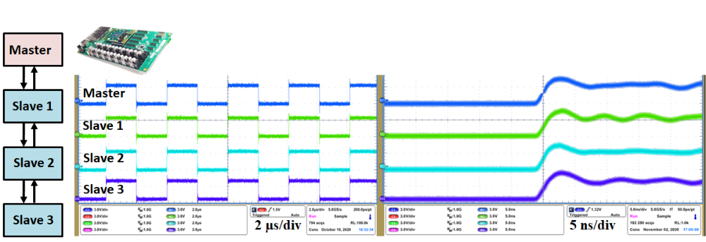
A communication network including one master and three slave PEBB controllers in a linear daisy chain topology is built in order to verify the synchronization performance. The controllers are connected through SFP transceivers running at 5 Gbps. The FPGA local clock frequency on each controller is set to be 125 MHz, and a local time counter is generated based on its own clock, which is utilized to coordinate the synchronous operation of different controllers. A square wave based on the local time counter is utilized to measure the synchronization accuracy among different controllers. The synchronization performance for four nodes is shown in Fig. 2. Keeping the system running for around 2 hours, the jitter (peak to peak) of 1 ns is observed. The total sampling points is 182,280 samples.


