LIBRARY
A Constant-Current ZVS Class-E DC-DC Converter with A Loosely Coupled Transformer with PCB Windings

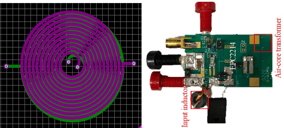
The converter can be separated with a class-e inverter and a compensation network. The Class-e inverter can be equivalized with a voltage source in series with a capacitor. The fundamental output voltage can be constant if the capacitor is compensated at a certain switching frequency and the load is resistive. The CC output is realized by adding a CLC network to the Class-E inverter. Capacitor C1 and C2 compensate the self-inductance at the primary side and secondary side to realize a resistive load. For duty ratio (D) equal to 0.5, the switching frequency needs to be 1.29 of the resonant frequency of Lin<\sub> and Cin<\sub>. The leakage inductances Ll1<\sub> and Ll2<\sub> need to be large enough to suppress high-order harmonics. In this work, the self-inductance is 600 nH and mutual-inductance is 360 nH. The switching frequency is 6.78 MHz and the output current is 700 mA.
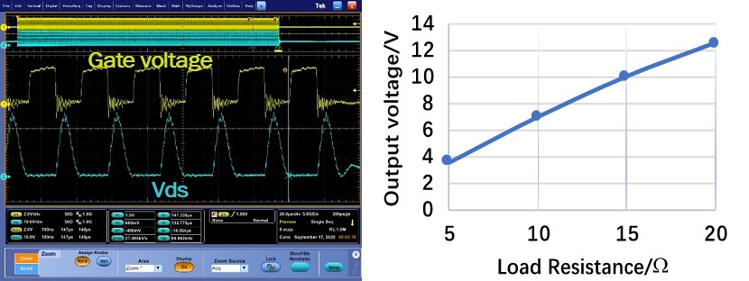
Fig. 2. shows the testing results with 10 V input and different load-resistances. ZVS is always maintained within the load range and output voltage increases linearly with the load-resistance, which is the characteristics of CC output. The peak efficiency of the converter is 80%.
In summary, this work demonstrated the principle of realizing CC output on the Class-e dc-dc converter with an air-core transformer. The work can be a good candidate for high-temperature and low-profile applications with the elimination of magnetic cores. The efficiency can be further improved by optimizing the air-core transformer and will be discussed in the future.


