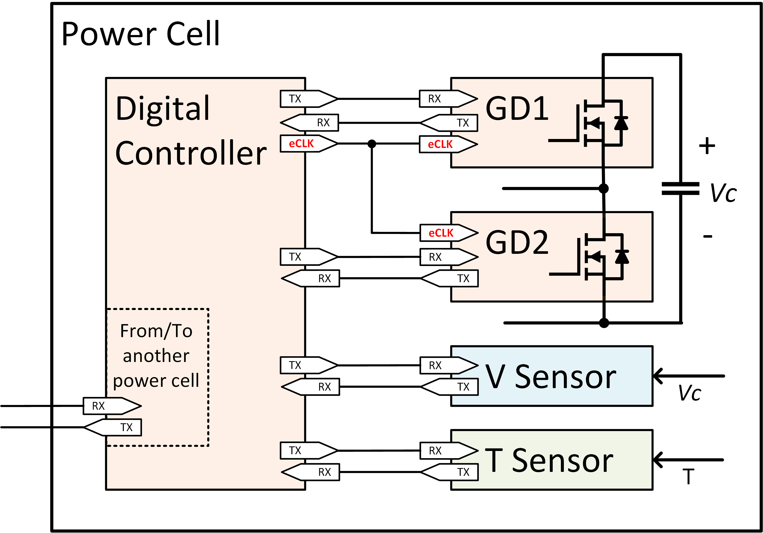
Fig. 1. Structure of the power cell.
The conventional approach for a controller to control gate drivers in a power electronics system is to send pulse width modulation (PWM) pulses from the controller to the gate drivers (usually two, four, or six are connected to one controller) and to do ADC conversion of signals from sensors as feedback to apply control. This is not a modular nor flexible approach since the controller usually has a limited number of inputs for sensors and a limited number of outputs for gate drivers. Additionally, modern gate driver modules have voltage, current, and temperature sensors for protection purposes, and a fault signal is sent as a signal to the gate driver. The main idea is to have a distributed system so that each sensor and gate driver can communicate with the controller and between them using some communication network and protocol. This time gate driver (GD) should be "smart" enough to receive commands from the controller and that some parts of control happen inside the GD itself. This way, the number of sensors could be reduced because gate drivers' sensors could be utilized for control purposes. Also, flexibility and modularity could be significantly increased. Control could be divided and distributed so that low-level control could be done in the gate driver.
Fig. 1 shows the internal structure of one power cell. As could be seen, it consists of two gate drivers for top and bottom devices, voltage, temperature sensors, and the local controller. Power cells could be combined to achieve the desired topology. Clock for synchronization purposes is not regenerated from communication, but it is physically distributed between the local controller and GDs. This approach brings good synchronization using relatively inexpensive communication hardware.
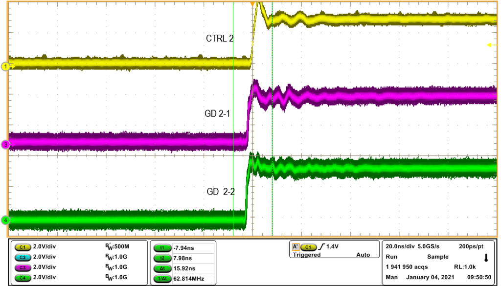
The key element of a system like this is synchronization between GDs and controller(s) (nodes of the system). Synchronization is tightly coupled with communication. The synchronization of timers in nodes is based on PTP (Precision Time Protocol - IEEE 1588). Synchronous timers allow us to "tell" GD or controller to execute some action at the exact moment with nanosecond precision. Fig. 2 shows the 8th bit of timers. It could be seen how well timers on the controller and both gate drivers are synchronized. It could be seen that the jitter is very small (~ 1 ns), and that the latency is in the two ns range.

Fig. 2. Timers synchronization.


