LIBRARY
Digital implementation of the multi-cell switching cycle control for modular multilevel converters

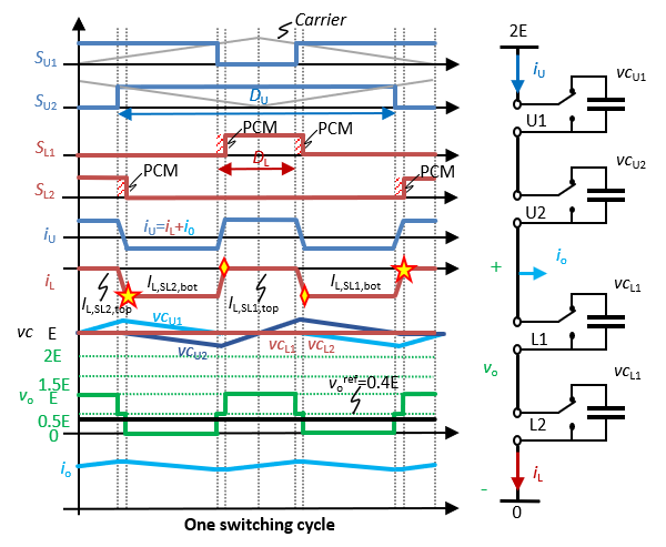
Switching cycle control (SCC) effectively eliminates this voltage line-frequency dependence, even enables the dc-dc mode operation of MMC benefiting a more than 100 times shrinking on required cell capacitance. Using 2-cell per- arm MMC as an instance, Fig. 1 demonstrates the typical working principle of the multi-cell SCC in dc-dc mode. To ensure the switching cycle capacitor voltage balancing, the top and bottom arm currents (iu and iL) are intentionally shaped to ensure the charge balancing of capacitor voltages (vcu1, vcu2, vcL1 and vcL2). Peak-current mode (PCM) modulation combined with on-line calculated current boundaries are adopted to precisely shape the arm currents, which is paramount for the SCC. As shown in Fig. 1, assuming the phase current flows out of the MMC phase- leg, the cell connection signals of the upper arm and lower arm (Su1, Su2, SL1 and SL2) are determined by average current mode and PCM modulation, respectively.
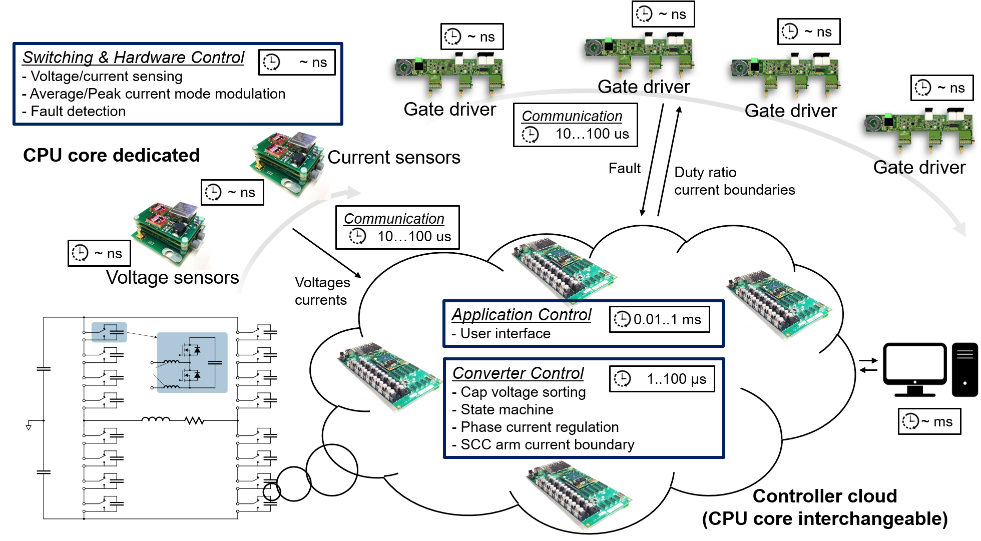
For MMCs, distributed control with a high degree of flexibility and scalability is obviously preferred. Yet the segmented arm current shaping in SCC demands nano-second synchronization accuracy among different controllers, which poses great challenges on digital implementations. In this article, based on the timing scale and accuracy, the SCC is separated into 3 control layers: naming the application control, converter control, and switching & hardware control layers. Control layer features are carefully investigated and mapped to custom- build, distributed controller clusters with sub-nano- second synchronization accuracy, as shown in Fig. 2. The switching & hardware control layers are implemented with dedicated CPU cores, while the other two control layers are implemented by a cloud of high-end controllers with reconfigurable CPU functions to enable a high degree of flexibility and reliability. Communication, task tables, and a scheduler mechanism are designed to coordinate the controller cloud. A detailed timing chart is also provided to help demonstrate and minimize possible digital delays in the system. The digital implementation is verified on a 4-cell per arm 2 MW 24 kV MMC in both dc-dc and dc-ac operations.


