RESEARCH
Modeling Resonant Converter in a Rotating Coordinate

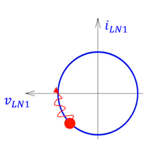
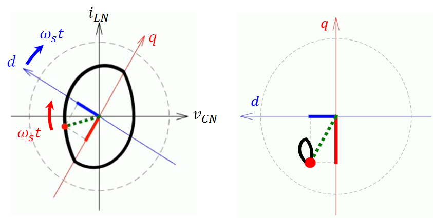
On the other hand, ac machine theory has dealt with sinusoidal waveforms for decades. By rotating the coordinate transformation, or dq-transformation, ac signals become dc signals. As a result, the average concept works again. If we look at the trajectory in the state plane of an SRC, as shown in Fig. 2(a), the state is rotating with the switching frequency ωS. Therefore, if the two axes, d and q, also rotate with ωS, the state becomes stationary with respect to the new coordinate, as shown in Fig. 2(b). In this case, the equilibrium state of SRC is clearly defined.
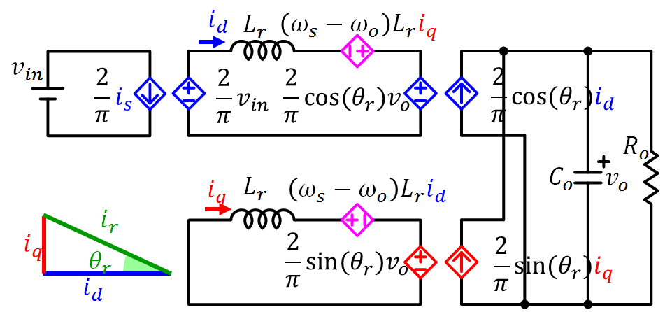
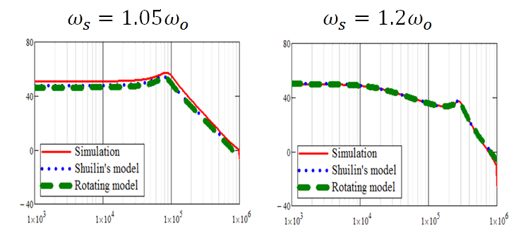
Since the average concept applies to an SRC on a rotating coordinate, the modeling process is as simple as that for a PWM converter. The average model of an SRC on a rotating coordinate is shown in Fig. 3. Compared with a simplified version of E. Yang's model, which was derived by S. Tian, the two models are almost identical. However, the latter went through complicated mathematical derivation and lengthy simplification. Using a standard perturbation process, the small-signal model of the SRC can be derived, and the simulation results are shown in Fig. 4. The two models match well with the simulation result. Nevertheless, the rotating coordinate method is both conceptually and mathematically easier to use to model a resonant converter.


