


LIBRARY
Droop Voltage Range Design in DC Micro-Grids, Considering Cable Resistance
Year: 2015
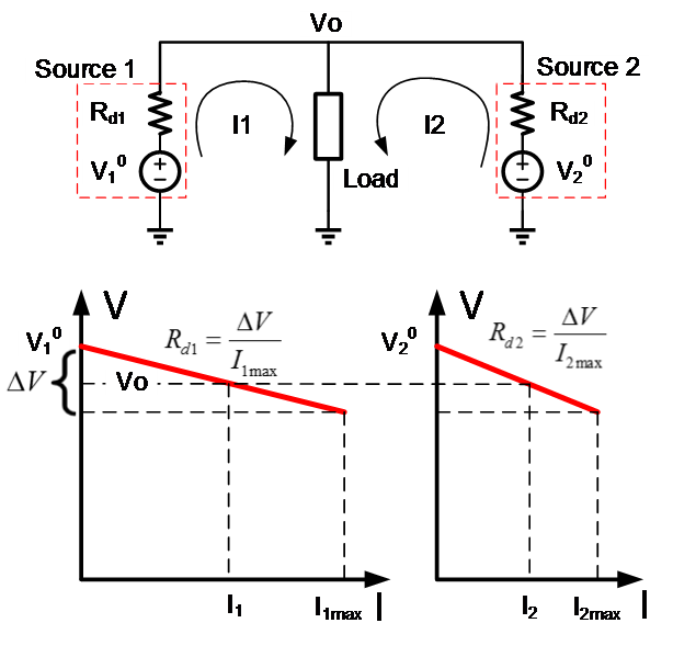
Fig. 1. Droop control in a 2-source 1-load DC system.
Though the droop principle is discussed in many papers, the practical design of droop in a DC system is seldom discussed. In real cases, cable resistance and voltage regulation errors will impact the load sharing performance with droop control. In addition, the voltage distribution within the DC system will be different from that in the ideal case.
In this paper, the impact of cable resistance and voltage regulation error on droop control was investigated. Cable resistance changes the load-sharing ratio among sources, while the voltage regulation error introduces a constant current error. To suppress the impact from cable resistance, larger droop resistance is preferred, but voltage regulation is sacrificed as a result. The cable size and possible voltage range for droop in a DC system are analyzed, and the quantitative relation between droop voltage range and unbalanced current was derived for 2-source sys-tems as shown in Fig. 2.
The worst-case scenarios for 3-source and multi-source multi-load systems were identified. Though proper distribution of sources and loads helps relieve the load sharing unbalance, the worst-case scenario remains the same as was discussed for the 2-source 1-load system. Therefore, the conclusion for the 2-source system can be used to estimate the worst-case scenario for the multi-source system. The DC system designer can use the quantitative results from this paper to choose proper droop voltage range and guarantee the sharing unbalance within the required range. If necessary, detailed load sharing results for a particular configuration can be calculated using a numerical method.
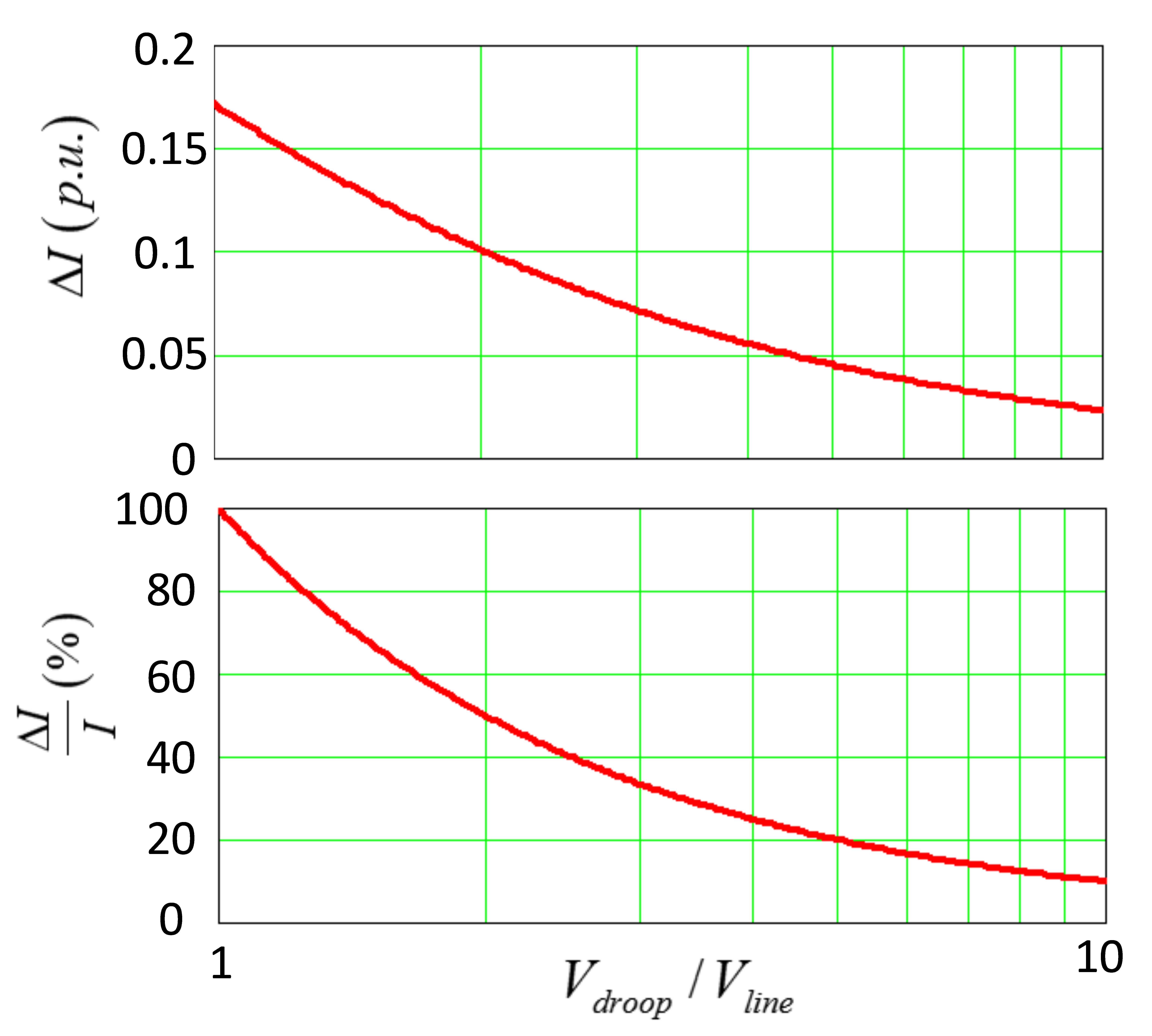
Fig. 2. Sharing error as a function of droop voltage range
