LIBRARY
Resonant Converter with Coupling Independent Resonance for Wireless Power Transfer Application

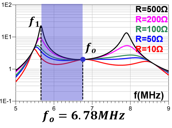
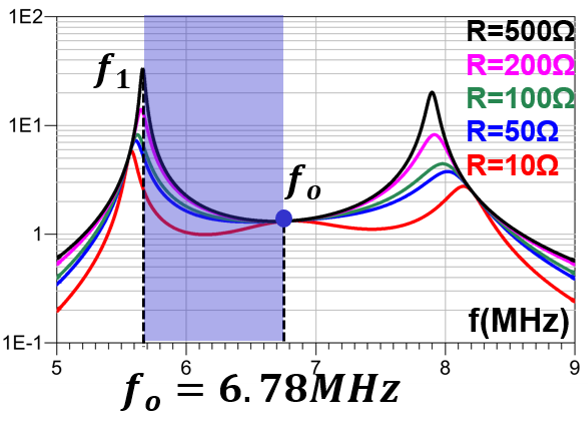
The LCCL-LC resonant converter, as shown in Fig. 1 is formed by adding two capacitors (Cp and Cs) in LCL resonant converter. Cs is added first to form a coupling independent resonant frequency fo. The formula of resonant frequency is shown in Eq.1 in which Ls is the self inductance of the receiver coil. Self inductance is independent of coupling, therefore, the resonant frequency is independent of coupling between the transmitter and receiver coils. Cp is added to make sure that input impedance at fo is inductive, which is necessary for the ZVS operation of the primary switching device. From a gain characteristics point of view, Cp creates a parallel resonant frequency (f1) lower than fo. Then, f1 improves the ZVS region of this converter so it is similar to the LLC resonant converter.
The gain characteristics of the LCCL-LC resonant converter in different coupling conditions are shown in Fig. 2. In this figure, it's easy to see that fo is independent of the coupling condition, which means that this converter can always operate at an optimal point in variable coupling cases. Besides, ZVS operation in the blue region can be guaranteed due to existence of f1. Therefore, the LCCL-LC resonant converter is very suitable for WPT applications and more topologies with similar characteristics will be provided in the full paper.
fo=1/(2(Lr Cr ))=1/(2(Ls Cs ))
Eq. 1.


