LIBRARY
On the Measurement of Switching Energy

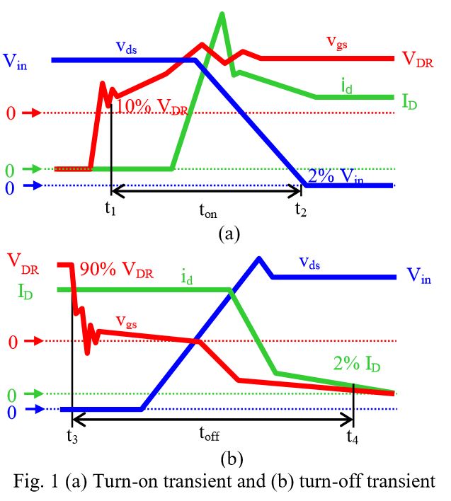
Other manufacturers consider the starting point of the turn-on transient to be when vgs in-creases to 10% of VDR and ends when vds decreases to 10% of VCC. The starting point of the turn-off transient is defined to be when vgs decreases to 90% of VDR and ends when vds increases to 90% of VCC.
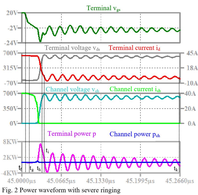
Both of these methods ignore the losses caused by the switching ringing, which are consid-ered by some researchers. The turn-on transient is defined as starting when the id is non-zero and ending when the peak-to-peak current of the ringing is 10% of ID. The turn-off transient is defined as beginning when id begins to decrease and ends when the peak-to-peak current of the ringing is 10% of ID. This method includes the ringing loss but also contains part of the conduction loss. The proportions of the conduction losses that are included are different for different devices under various test conditions. This would make a comparison of the devices unfair.
This work describes a method to calculate the switching energy independent of transient timing. The total loss energy E is calculated from switching energy Eswitch, conduction energy Econd, steady-state current I, resistance Rds(on) when the MOSFET is fully on, and on-time Ton by E = Eswitch + Econd = Eswitch + I2Rds(on)Ton. Constant I is realized by a current source in simulation or large inductor in practice. "Constant Rds(on)" is approximated by "negligible variation in Rds(on)" by limiting the temperature rise induced by the power pulses in one period. By assigning Ton to be a chosen on-time Ton1, the associated total energy in one cycle E1 could be obtained by simulation or experiment. By assigning Ton to be value Ton2, the associated E2 becomes known. The switching energy is then calculated by Eswitch = (E1Ton2 - E2Ton1)/(Ton2 - Ton1). The switching energy calculated by the previous three existing methods based on the simulated power waveform differs from the simulated channel energy by more than 9%. The difference is reduced to 0.3% by using the proposed method.


