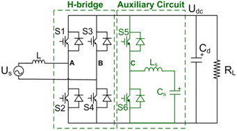
Fig. 1. System topology for the active ripple energy storage method.
One of the important characteristics of the single-phase rectifier is the low-frequency ripple power on the dc link when the ac input voltage and current are sinusoidal. The converter power has both a dc and a ripple component with the ripple frequency to be twice that of the ac input frequency, and can therefore cause a second-order frequency ripple in dc link voltage. To limit this low frequency ripple, a bulk dc link capacitor is usually required, which results in large converter volume and low power density. The electrolytic capacitors often used in this case for their cost and energy density advantages can also pose problems due to their inferior life-time and reliability. To improve the power density of a single-phase rectifier, it is essential to reduce the dc-link capacitor required for filtering the low-frequency ripple energy.
A bidirectional buck-boost converter is connected at the output of the typical single phase PWM rectifier. An auxiliary capacitor with capacitance Cs is used as an energy storage element. We control the bidirectional converter as a buck mode when ripple energy needs to be stored in the Cs. It is controlled as a boost mode when ripple energy needs to be released back to the dc link. A dc link capacitor with capacitance Cd is still needed at the output of the PWM rectifier. Cd can be considerably smaller than the capacitance required in the conventional method, since it needs only to filter the switching ripple energy and the residual second-order harmonic ripple energy not fully absorbed by the auxiliary capacitor Cs. The switching ripple energy, results from both the PWM rectifier and the bidirectional buck boost converter.
Finally, the simulation and experimental results are shown for verification purposes.

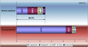
Fig. 2. Main components volume comparison.

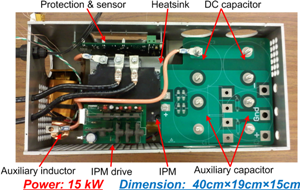
Fig. 3. 15kW single phase rectifier prototype.

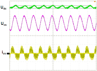
Fig. 4. Experiment waveforms when the auxiliary circuit is active (15kW).


