RESEARCH
High-Efficiency High-Power-Density 48/1V Sigma Converter Voltage Regulator Module

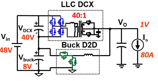
In this work, a one stage sigma converter is proposed for a high efficiency solution in such applications. The sigma converter consists of two series connected converters from the input side and parallel connected from the output side as shown in Fig.1.
Comparing the two stage solutions, the power flow in the sigma converter is shared between two converters. A ratio is determined with the input voltage across each of them. For a higher efficiency solution, an unregulated LLC converter (DCX) was designed to have a 40V input while the remaining 8V is applied to the buck converter responsible for the output voltage regulation. This allows the majority of the power to slowly flow through a higher efficiency path. A small portion of the power flows through the less efficient buck converter resulting in a higher total efficiency.
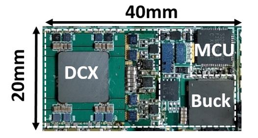
A PCB winding Matrix transformer structure integrating four transformers in one core was adopted for the LLC-DCX. A one turn PCB winding inductor was used for the buck converter resulting in a very high density solution reaching 420 W/in3 as shown in Fig. 2.
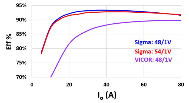
The prototype was experimentally tested achieving a maximum efficiency of 93.4% with a heavy load efficiency of 91.6%. The converter efficiency was measured at different input voltages and achieved a higher efficiency than the state of the art solution from VICOR as shown in Fig.3.


