


LIBRARY
Derivation of High Efficient Robust PV Inverter
Year: 2010
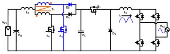
Fig. 1. Proposed interleaved boost plus buck PV inverter.
An interleaved boost-buck dc-dc converter is proposed as the first stage with regulated output inductor current, and a full-bridge unfolding circuit with 50- or 60-Hz line frequency is applied to the dc-ac sage, which will unfold the rectified sinusoid current regulated by the dc-ac stage into a pure sinusoidal current, as shown in Figure 1. The buck mode will work if the input voltage is higher than the instant grid voltage, otherwise the boost mode will work. These two modes work separately as shown in Figure 2. After modeling of the inverter, it is known that the smaller L1 is the better controller can be designed and the better performance can be obtained. Thus, interleaved boost is proposed in order to have the same current ripple. The experimental results are shown in Figure 3 (a) and (b).
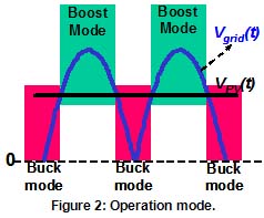
Fig. 2. Operation mode.
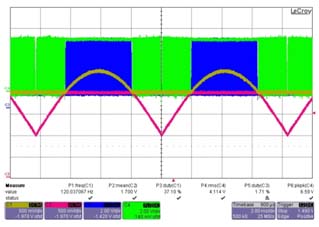
Fig. 3. (a) Experiment Results of PWM Signals.
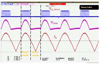
Fig. 3. (b) Experiment Results.
