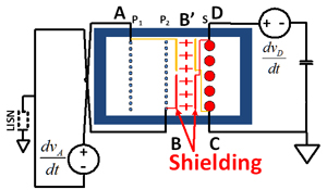
Fig. 1 Balance Double Shielding.
Isolated converters are widely used in telecom, server systems and point-of-load conversion for portable electronics. These applications must meet the EMI standard. In an isolated converter, the transformer is a main path of the common mode current. Methods to reduce transformer noise have been widely studied. One effective technique is using a shield between the primary and secondary winding. In this paper, the EMI noise transferring path and the EMI model for typical isolated converters are analyzed and the survey about different methods of shielding is discussed. Pros and cons are analyzed. The balance concept is then introduced and our proposed double shielding, which uses a balance concept for the wire winding transformer is raised. Fig. 1 shows a two layer shielding that is added between the primary and secondary windings. However, the shielding is wound and divided into two parts. In one part of the shielding, one layer is connected to A and the other layer is connected to C. In the other part of the shielding, one layer is connected to B and the other layer is connected to D. Hence, through the shielding, CAC and CBD are created, and we can adjust the value of CAC and CBD by changing the wounded position. It can control the parasitic capacitance accurately and is easy to manufacture. Next, a newly proposed single layer shielding for a PCB winding transformer is discussed. The shielding is rotated 180 degree, as shown in Fig.3. On half of the windings, the voltage of the shielding is higher than the secondary winding and there is a current flow from the shielding to the secondary winding. On the other half of the winding, the voltage of secondary winding is higher than the shielding and there is current flow from the secondary winding to the shielding. Although the voltage is not identical between the secondary winding and the shielding, the current is circulating between them. Hence there is no common mode noise current flowing through the transformer. The experiment results are provided to verify the methods.
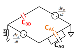
Fig. 2 Bridge Circuit.
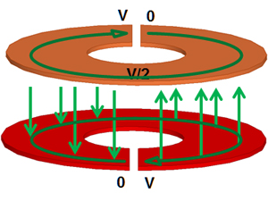
Fig. 3 Single Layer Shielding for PCB Winding.
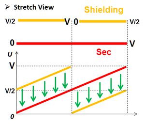
Fig. 3 Single Layer Shielding for PCB Winding.


