


LIBRARY
Analysis of Phase Locked Loop (PLL) Influence on DQ Impedance Measurement in Three-phase AC Systems
Year: 2013
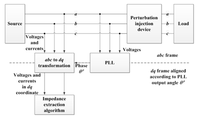
Fig. 1. Impedance measurement setup of three-phase systems represented in abc coordinates.
Figure 1 explains the PLL's role in the measurement path. The analysis shows that it changes the measured voltage and current spectrum, thus changing the impedance result. For this rea-son, the PLL bandwidth in existing systems is much smaller than the lowest frequency of the measured impedance, strongly increasing the measurement time. However, the effect can be compensated offline using:
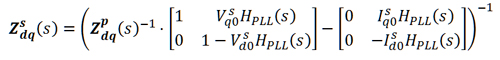
where Z_dq^s (s) is the correct system impedance, Z_dq^p (s) is the measured impedance, H_PLL (s) is the transfer function of PLL, and all the variables with 0 in subscription are steady state value of the variables. Figure 2 demonstrates the compensation result. It can be seen that the PLL causes a huge error on the measurement of impedance of a diode rectifier. But the compensation can correct the result back to very close to the real impedance. The offline compensation enables a higher PLL bandwidth and a significantly faster measurement system.
PLL's effect on perturbation injection is also analyzed in the paper. It has no influence on the perturbation if no DC component is injected. Therefore, the bandwidth of the injection PLL does not affect the measurement.
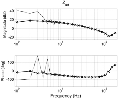
Fig. 2. Impedance correction sample Extracted diode-rectifier impedances. Solid line: no PLL; dotted line: 50 Hz bandwidth; 'x' markers: result back calculated from 50 Hz result).
