LIBRARY
EMI Filter Design Considering In-Circuit Impedance Mismatching


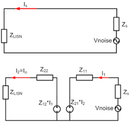
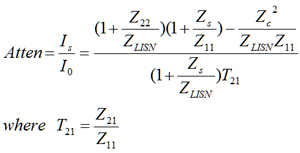
It is evident that the noise attenuation comes from three terms: Z22/ZLISN, ZS/Z11 and T21. Other terms like ZS and ZLISN are fixed by the design and the standards used for EMI compliance. For the differential mode (DM) filter the impedance ZS is decided by the large input dc-link capacitor of the converter and when ZLISN equals 100%u2126 (standard LISN). Thus, for a simple LC filter and a very small ZS, the inductor (L) of the filter should be facing the converter so that Z11 can be easily made greater than ZS, which results in ZS/Z11 becoming very small. On the other hand, if the capacitor (C) of the LC filter is facing the LISN, this will make Z22/ ZLISN small as well. In this way the attenuation will be decided by T21 only. In order to make the attenuation larger, T21 should be as small as possible, which can be easily achieved when the LC filter with L is facing the converter Z11 = ZL ZC and Z21 = ZC.
A similar understanding is created in the case of the common-mode (CM) filter. Here contrary to the DM - LC filter, the C should be facing the converter as the CM capacitance of the converter is usually very small thus causing ZS to be very large. Moreover, in CM the LISN impedance is only 25 ω so the L should face the LISN. Such a choice will provide the optimum impedance mismatching in the case of CM as it will make both ZS/Z11 and Z22/ZLISN very large, which causes the attenuation to be large as well.


