


LIBRARY
Bi-directional PHEV Battery Charger based on Normally-off GaN-on-Si Multi-Chip Module
Year: 2014
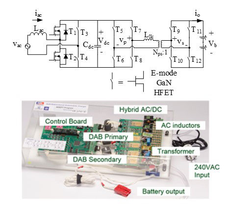
Fig. 1. GaN bi-directional battery charger topology and prototype.
The full bridge topology is used for the bi-directional AC/DC stage. In the AC/DC stage modula-tion, one of the phase legs only flips the polarity of the midpoint every half line cycle. This ena-bles the possibility to use a very large Si MOSFETs to optimize the conduction loss since the switching loss will be negligible due to 60Hz switching. DAB is one of the most widely researched bi-directional DC/DC topology because of the zero-voltage-switching and fixed fre-quency. Except for the 60Hz-commutation phase leg in the AC/DC stage, all the rest of the phase legs are built with an enhanced mode high voltage GaN HFETs from HRL Laboratories. The phase leg is packaged in a multi-chip-module with built-in gate driver and decoupling capaci-tors. The module realizes low parasitics, low switching overshoot and low switching energy.
The prototype shown in Fig. 1 consists of three building blocks of full bridge (designated as Hybrid AC/DC, DAB primary and DAB secondary), magnetics and the control board. High switching frequency leads to smaller magnetic size. The control board is for general purposes and can be reduced in the final implementation.
Experimental waveforms are shown in Fig.2. The test was conducted at 165Vrms AC input, 250V voltage at the battery and 1kW output power. By allowing the 120Hz ripple into the battery, the DC link capacitance can be significantly reduced so that only ceramic capacitors are used. The achieved system efficiency is 92.0%, and if doing DC charging, the efficiency is 94.2%.
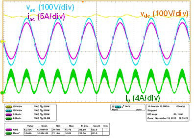
Fig. 2. Charging system waveforms at 1kW with sinusoidal charging. Conditions: Vac = 165V(rms), Vdc = 250V, Vb = 250V, Io(avg) = 4A.
