


LIBRARY
Evaluation of GaN-Based MHz Interleaved CRM PFC Converter
Year: 2014
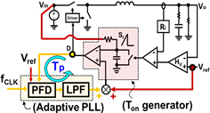
Fig. 1. (a) Adaptive PLL loop: Block diagram.
This paper first provides an accurate small-signal model to understand the dynamics of the PLL loop, and gives design guidelines for the Low Pass Filter (LPF) of PLL to avoid the stability problem. Then, an adaptive PLL loop is proposed to maintain a constant Tp bandwidth over a wide duty cycle range. Thus, the PLL loop design becomes simple and has fast tracking to fclk without interfering with constant on-time control loop. As shown in Fig. 1, a proposed adaptive PLL loop maintains a constant gain by using Vin and Vo feedforward at on-time generator, and Vo feedforward at Phase Frequency Detector (PFD) of PLL. Secondly, a novel hybrid interleaving structure is developed with a comparable noise immunity and transient response as the PLL method, while the number of PLL loops is greatly reduced. For a 4-phase operation as shown in Fig. 2, it contains two phase managers that maintain a 180° phase difference for each of the two phases, and only one PLL locks 90° difference between D1 and D3. 3 PLL loops are saved when compared with the PLL method. Fig. 3 shows PWM overlapping during transient naturally. Finally, the simulation result based on the state-of-art filter model of the laptop VR demonstrates the constant output impedance design for an AVP over a wide duty cycle range.
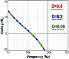
Fig. 1. (b) Simulated Tp Loop gain.
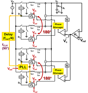
Fig. 2. (a) 4-phase hybrid interleaving: Block diagram.

Fig. 2. (b) Transient response.
