LIBRARY
Adaptive Synchronous Rectifier Driving Scheme for LLC Resonant Converter

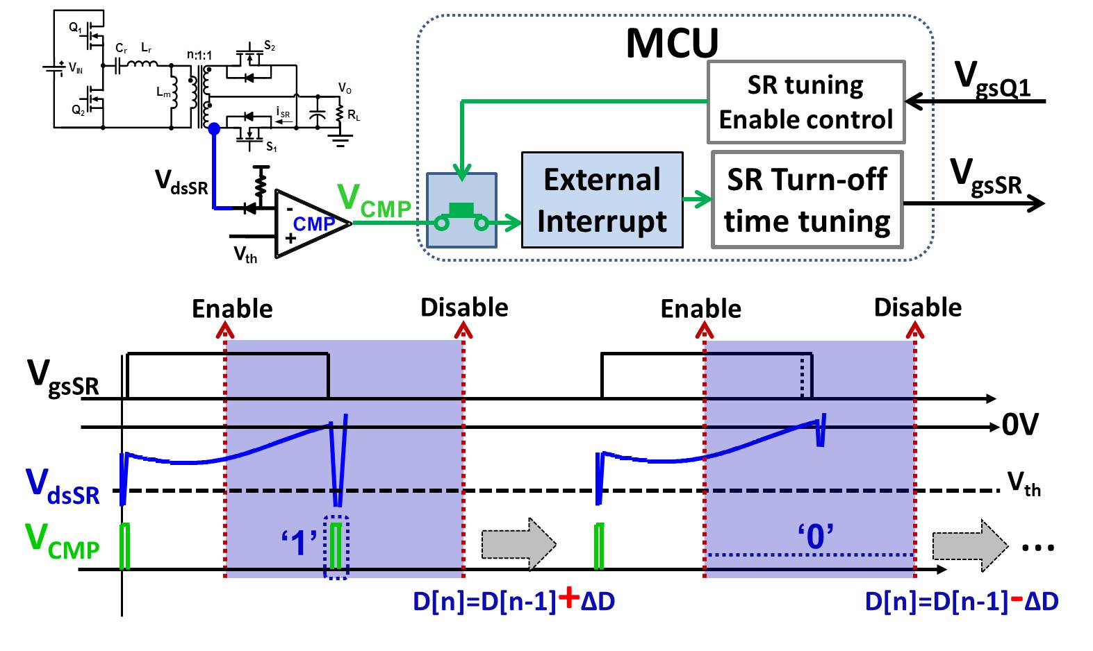
The drain to source voltage of the synchronous rectifier is sensed and compared with the threshold voltage in order to detect the paralleled body diode conduction. For the conventional LLC converter, the SR turn-ON time is synchronized with the primary side switches, and the SR turn-OFF time is tuned to eliminate body diode conduction based on the output of the comparator, which is in turn connected to the external interrupt of MCU, as shown in Fig. 1.
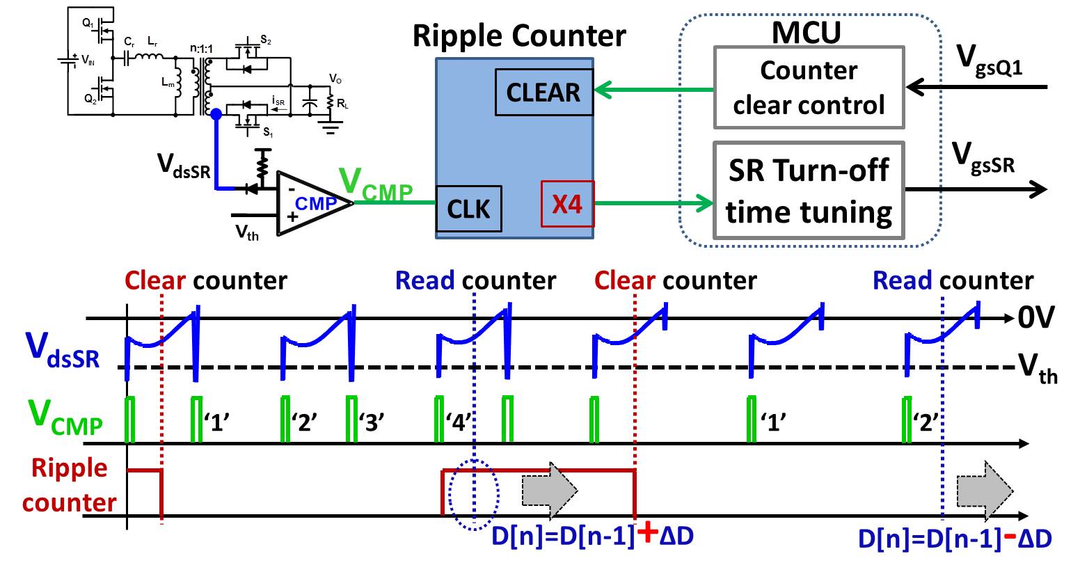
For the high frequency LLC converter, if the SR turn-OFF time is tuned every switching cycle, the CPU of the MCU will be busy most of the time. To release the burden on the MCU, the output of the comparator is connected to a ripple counter instead of the external interrupt of the MCU, as shown in Fig. 2. The SR turn-ON time is still synchronized with the primary side switches, but the SR turn-OFF time is tuned based on the status of the counter's output. The counter is cleared every third switching cycle for a 500kHz LLC converter.
Adaptive SR driving for a conventional LLC converter is verified on a 130kHz LLC converter with MCU TMS320F2808. Adaptive SR driving for a high frequency LLC converter is verified on a 500kHz LLC converter with MCU TMS320F28027. The desired performance is achieved in both cases.


