LIBRARY
Hybrid Modulation for Neutral Point Voltage Reduction in DC-fed Three-Level Motor Drive Systems

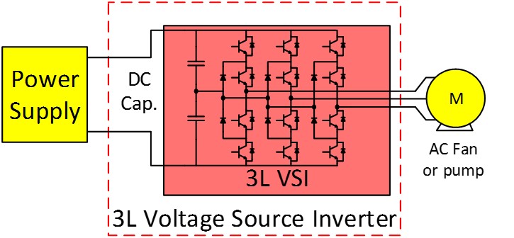
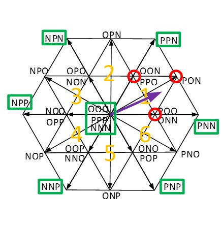
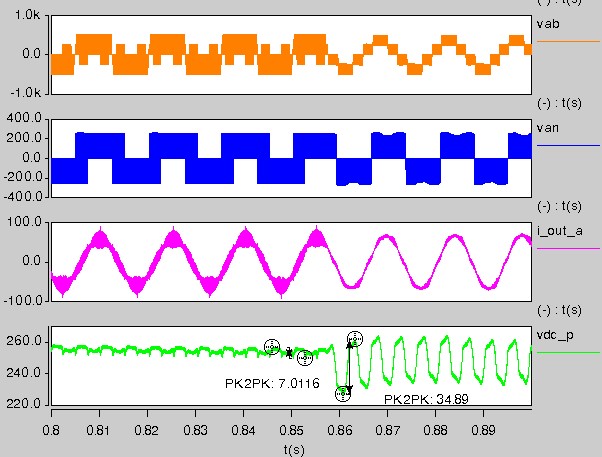
In NPC 3L inverters, since each phase leg has three output voltage levels: Vdc/2 (P), 0 (O), -Vdc/2 (N), there are a total of 27 switching states and 18 output voltage vectors for the three phases, as shown in Fig. 2. There have been many publications about the modulation methods for NPC 3L inverters. Different optimization goals, such as minimum loss or harmonic distortion can be achieved by using the redundant switching states. The neutral point voltage calculation model is presented to study the large NP voltage ripple for three level modulation during the startup process. Moreover, the possible overvoltage issue on the semiconductors considering the different switching speed of the devices for two level modulation in three level NPC converters is analyzed in detail. A zero neutral point voltage ripple modulation (ZNPVR) method is proposed to limit the NP voltage ripple and avoid overvoltage on the devices when the output fundamental frequency is low. When the output fundamental frequency is high, the modulation can smoothly transit to normal NTSV modulation for lower ripple and higher efficiency. Figure 3 shows the modulation method transition from the ZNPVR method to the NTSV method, which shows the effectiveness of ZNPVR modulation method.


