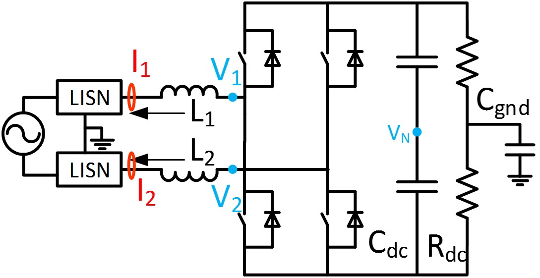
Fig. 1 : Single Phase PFC with H-Bridge Converter
PWM converters have made a significant contribution when it comes to achieving energy conservation, and improving system performance in many applications, such as transportation systems and renewable energy systems. In single phase applications, H-bridge converters, such as the VSI or PFC circuit (shown in Fig. 1) are commonly used due to their good performance. In such applications, certain electromagnetic interference (EMI) standards must be met to ensure that the system is working normally, and filters are inevitable in order for these systems to meet applicable standards, which represents a big portion of the total size and cost of PWM inverters. EMI models are necessary for an optimized EMI filter design. The conducted EMI noise is separated by common-mode (CM) and differential-mode (DM) according to the conventional theory, each mode of the noise is dealt with the respective section of an EMI filter. However, in real applications, there is additional noise-coupling mode, called the mixed mode (MM), that has a significant impact of the filter design effectiveness and needs to be dealt with.
Based on the time domain voltage, current relationship and the definition of DM and CM noise source and noise current, a noise prediction model is proposed in frequency domain with the consideration of system symmetry regarding the noise propagation path impedance. The model indicates that the mixed mode noise is the coupling between the CM/DM noise source and the DM/CM noise current due to circuit asymmetry. With the noise source calculated and circuit impedance measured or modeled in frequency domain, the mixed mode noise can be predicted based on the proposed model.
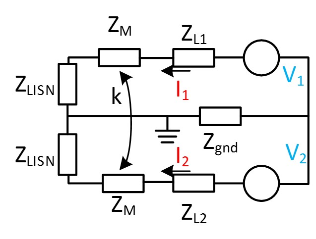
Fig. 2 : EMI model in frequency domain
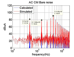
Figure 3. (a) EMI noise comparison (predicted: blue; Simulated: red CM noise with symmetric load
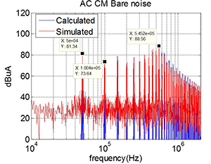
Fig. 3. (b) CM noise with asymmetric load
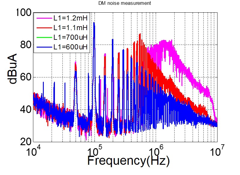
Figure 4. (a) Measured EMI noise with different circuit asymmetry CM noise with asymmetric load
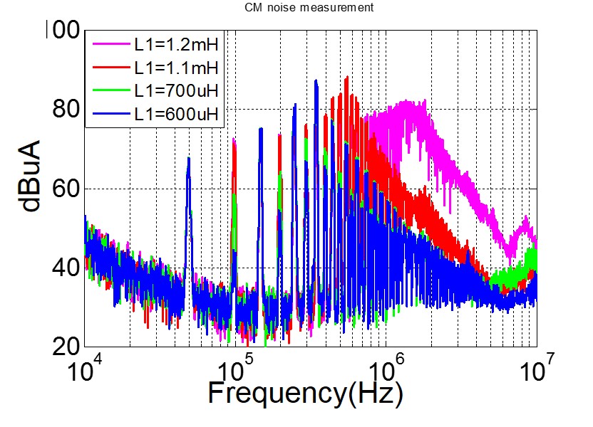
Fig. 4. (b) DM noise with asymmetric load


