


LIBRARY
Modeling of Plate-Core Inductors and Coupled Inductors
Year: 2016
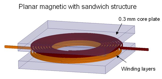
Fig. 1. 3D structure of plate-core coupled inductor with 5 5 mm2 foot-print and 0.3 mm core height.
Motivated by the finite-element analysis (FEA) plot of flux lines, a proportional-reluctance, equal-flux (PREF) model is developed to find the magnetic field by dividing the reluctance into several tubes that carry the same amount of flux. The methodology to construct the tubes is giv-en, and the ratio of the magnetic field versus space is found from the ratio of the flux over the cross-sectional areas. The inductance, ac winding loss, core loss, and leakage inductance are derived based on the modeling result of the field. Prototypes made of a flexible circuit for sin-gle-winding inductors are tested with different layouts to verify the model.
Fig. 2 shows the modeled flux lines of a plate-core inductor with 16 turns. The flux in the core and the air gap can be modeled accurately based on the reluctance calculation. The mag-netic field found from the ratio of the flux over the cross-sectional area of the tubes matches very well with simulation results. The magnetizing inductance based on the field distribution is verified by both FEA and experimental results. A preliminary design procedure is delineated with an example for the specified magnetizing inductance and dc quality factor. The winding loss cal-culated from the 2D method is discussed, as are the errors caused by the cylindrical coordinates. The methodologies for core loss calculation and leakage inductance calculation of coupled-inductors are also described.
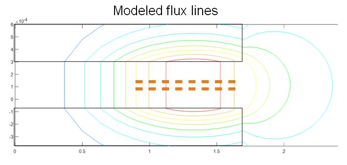
Fig. 2. Flux lines from proportional-reluctance, equal-flux model.
