LIBRARY
Modeling of Voltage-Controlled Capacitor (VCC) in Dc-Dc Converters

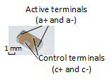
This paper presents a four-terminal VCC that varies from 20% to 100% of the rated capacitance (1 μF) with a control voltage from half of the voltage rating to 0 V. The prototype is shown in Fig. 1.
Models of nonlinear capacitors vary from the application. The C-V model is commonly used in dc-dc converters where the ac component is quite small compared with the dc component in capacitor voltages. In the C-V model, a capacitor current is generated only by a voltage change, such as a fixed capacitor even though a capacitance change is not considered another current source. Only the C-V curve, which can be measured by an impedance analyzer, is required in this method.
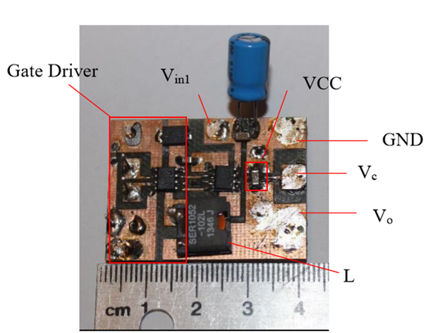
The VC was employed as an output filter of a buck converter with input of 12 V, output of 5 V, and switching frequency of 500 kHz to demonstrate its impact of controllability on the voltage ripple. The experiment hardware is shown in Fig.2. Simulation based on the C-V model showed an 8% error with an experimental waveform, which verified the effectiveness of the model in dc-dc converters. The comparison of simulation and experiment results are shown in Fig. 3. Future work will be focused on the design of the driver and closed-loop control of the VCC in other applications and circuit topologies.


