LIBRARY
Small-Signal Terminal-Characteristic Modeling of Three-Phase Droop-Controlled Inverters

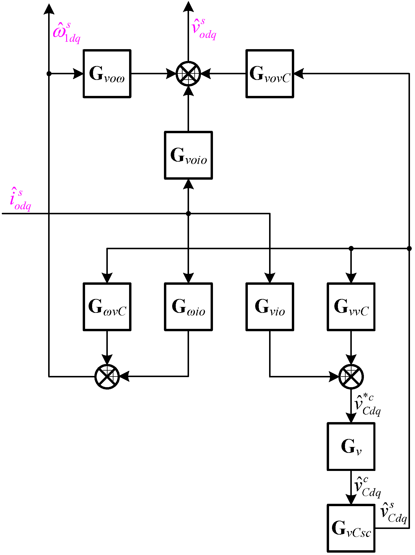
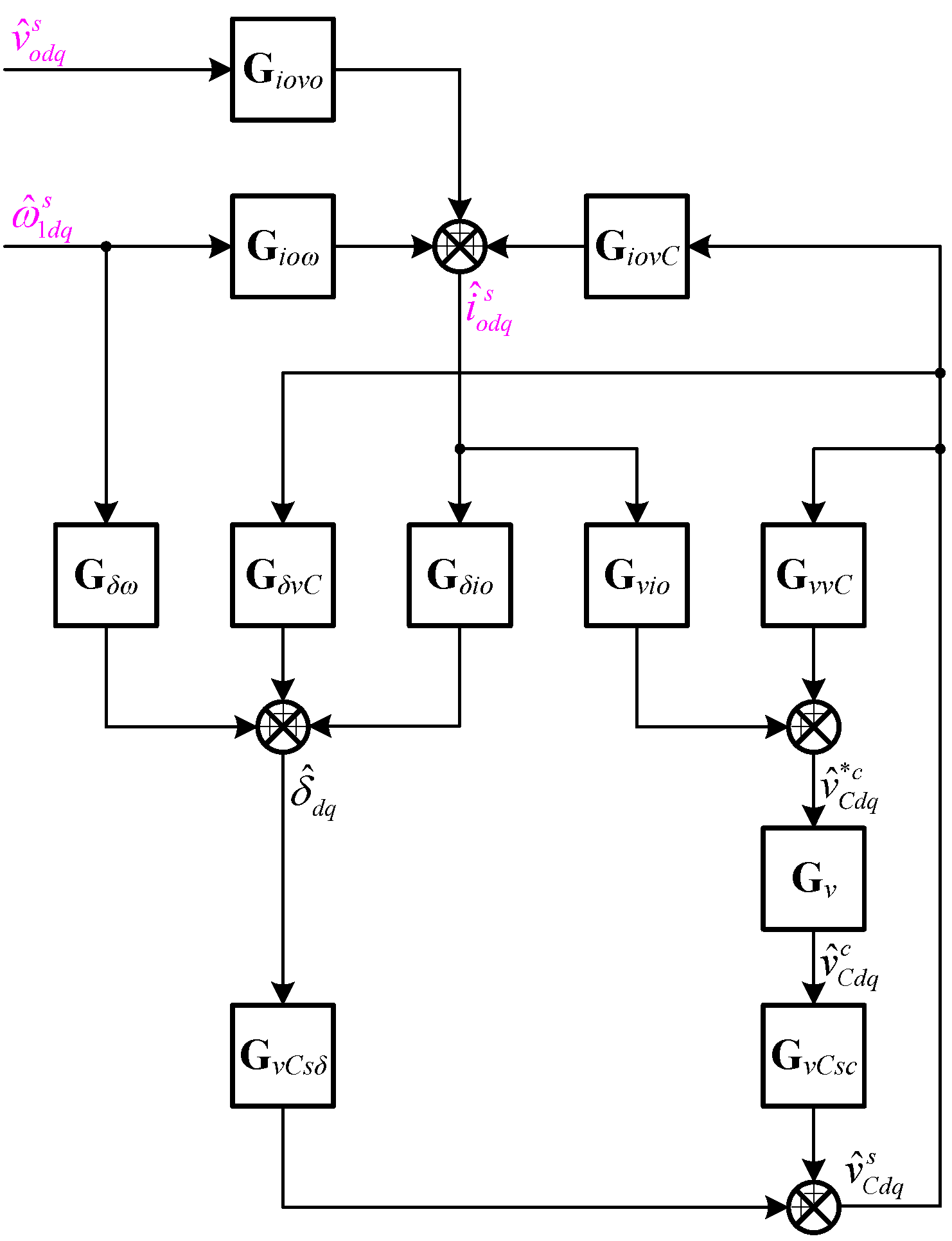
This paper proposes a small-signal terminal-characteristic model of the three-phase droop-controlled inverter in the synchronous reference frame (SRF), covering the behavior of funda-mental angular frequency. Firstly, the droop-controlled inverter can operate in both voltage mode and current mode, where its terminal characteristics are totally different. Since the inverters have different excitations and responses they are modeled respectively in this paper. Secondly, in each operation mode, the small-signal model of the power stage and the control system are modeled in the system SRF aligned to the terminal ac voltage, considering the dynamic of fun-damental frequency. Finally, we created full small-signal models of the three-phase droop-controlled inverter that covers the behavior of the fundamental frequency in both the power stage and control system in both operation modes, and the analytical expressions of the terminal-characteristics are derived. The proposed model is very beneficial for stability analysis of the distributed generation, covering the droop-controlled inverter in both grid-tied mode and islanded mode, which will be investigated in future publications.


