


LIBRARY
Digital Constant On-time V2 Control with Hybrid Capacitor Current Ramp Compensation
Year: 2018 | Author: Pei-Hsin Liu | Paper: D2.7
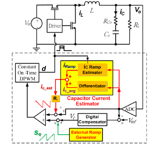
Fig. 1. Block diagram of the proposed digital V2 control with hybrid capacitor
current ramp compensation.
current ramp compensation.
V2 control with capacitor current ramp compensation has faster transient response, compared with the external ramp compensation and inductor current ramp compensation. In the analog implementations, several papers have demonstrated the superior performance of V2 control with capacitor current ramp compensation. Recent development of digital control for dc-dc switching converters has shown many unique capabilities such as digital communication, programmability, auto-tuning, and efficiency optimization.
For that reason, this paper is proposing a digital V2 control scheme with capacitor current ramp compensation. In the proposed digital implementation, an additional external ramp is added to improve the small-signal property of the system. This addition creates a hybrid ramp compensation architecture. A capacitor current estimation technique is also proposed in which the estimator utilizes the sampled output voltage and pulse width modulation signal to generate the estimated waveform. No additional drift compensation loop is needed, thus resulting in a simpler and more cost-effective design when compared with the digital ac inductor current estimator.
The proposed digital constant on-time V2 control scheme with hybrid ramp compensation is shown in Fig. 1. For design purposes, the small signal model for the proposed control architecture is derived. The design guidelines and stability criteria are presented. The effectiveness of the proposed control structure and the current ramp estimator are verified by the simulation and experimental results. The proposed scheme shows better dynamic performance than the V2 control with digital inductor current ramp compensation, with a 70 percent reduction on settling time, and a 20 percent reduction on undershoot deviation, as shown in Fig. 2.
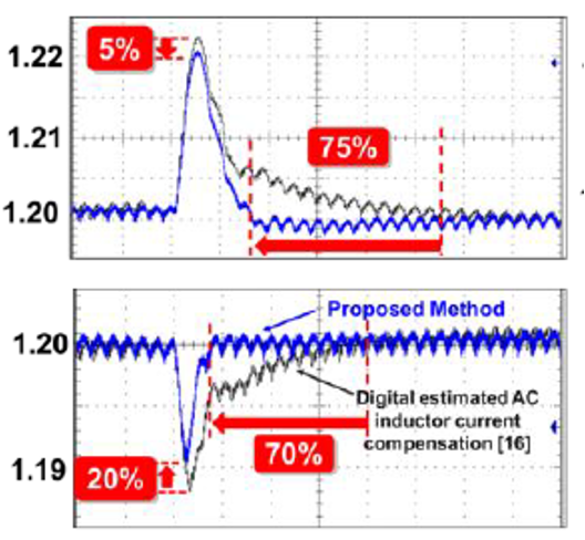
Fig. 2. Measurement and comparison of load transient response.
