LIBRARY
Resonant Cross-Commutated DC-DC Converter

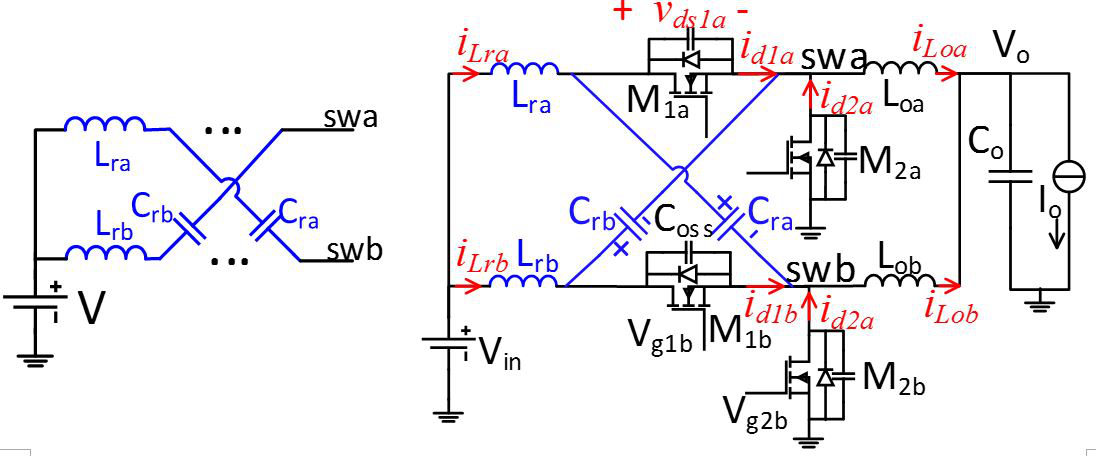
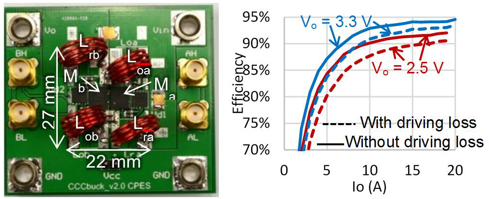
The operating principles and stresses are verified by an example with Vin = 12 V, Vo = 3.3 V, IoMax = 20 A, Ipp_Lo = 30% IoMax, VdsMax = 1.6 Vin, and fs = 2 MHz. Resonant cross-commutation has been proven effective (by simulation and experiment) in turning on the active switch at zero voltage over wide load range, and turning off the synchronous switch below 10 percent of IoMax at rated load, and below 25 percent of IoMax at half load. A 12 V3 V rccBuck converter switched at 2 MHz was designed and demonstrated to have peak efficiency of 93.5 percent at 20 A. The root mean square (rms) current in the resonant inductors is kept below 0.4 Io at half load by utilizing resonance between Lr and Cr. The duty ratio is extended and current stress for active metal-oxide semiconductor field-effect transistors (MOSFETs) is reduced compared with critical-mode buck converters. The concept of resonant cross-commutation can be extended to other topologies, such as boost converters, buck-boost converter, among others.


