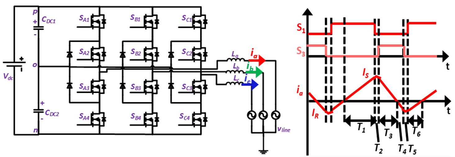
Fig. 1. 3-level NPC inverter with basic principle of ZVS turn-on with
TCM when AC mid-point is connected to neutral
Critical conduction mode (CRM)/Triangular current mode (TCM) control with ZVS turn-on for single phase converters has led to a significant improvement in efficiency at high switching frequencies (> 300 kHz). The need to push power converters to high switching frequencies results from the drive to achieve higher power density. High frequency operation helps to achieve higher power density as it leads to a significant decrease in filter volume which consumes most of the space in power converter systems. With recent advancements in wide bandgap devices technology, it is possible to operate at high switching frequencies with very low turn-off losses. However, turn-on losses in hard switching continuous conduction mode (CCM) are still significant, thus making it necessary to operate the inverter with zero voltage switching (ZVS) turn-on. A simple way of achieving soft switching in a three phase inverter is by connecting the DC bus mid-point to AC neutral, thus operating it as three single phase inverters in parallel. However, this configuration results in phase desynchronization and very high switching frequency variation. Switching frequency variation is minimized in TCM for a 2-level converter by clamping one of the phases. In this paper, it is shown how this method can be extended to three level inverters. As compared to 2-level converters, 3-level converters offer several advantages such as reduced common mode voltage (CMV). The same benefit is extracted in proposed 3-level TCM by making use of reduced CMV switching states. Two switching schemes are thus proposed which are applicable for any 3-level inverter topology. A 3-level NPC inverter is also considered in this paper. The modulation presented is compared with sinusoidal pulse width modulation (SPWM), it has lower losses as well as lower CMV. It is also shown that a huge reduction in inductor size is achieved by high switching frequency operation.
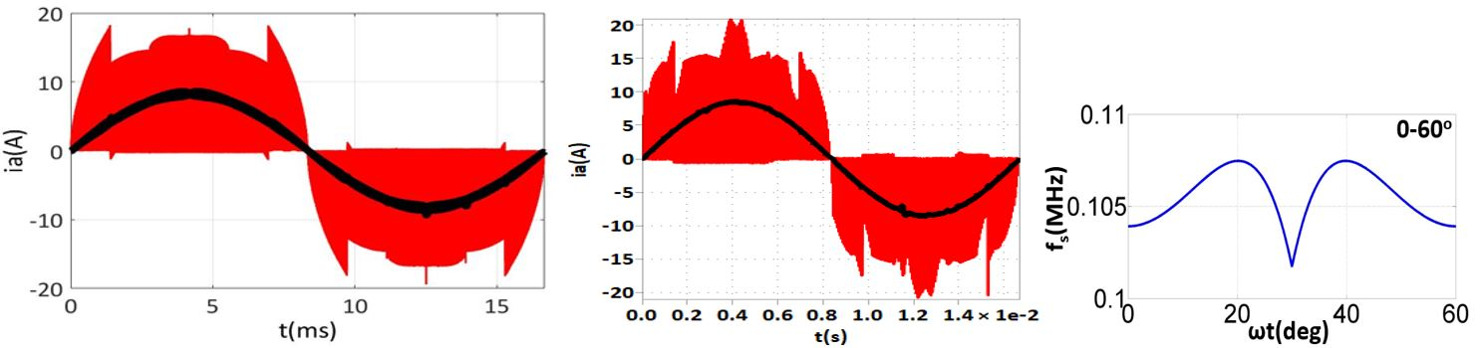
Fig. 2. Phase A current for a 5 kW, 900 Vdc, 480 V Vacl-l, L= 18 μH for (a) Scheme I &
(b) Scheme II. (c) Switching frequency variation for both the schemes


