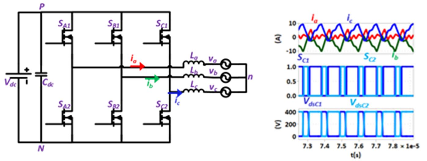
Fig. 1. Circuit schematic of three phase 2-level inverter with basic principle of ZVS turn-on with TCM
Critical conduction mode (CRM)/Triangular current mode (TCM) control with ZVS turn-on for single phase inverters has led to significant improvement in efficiency at high switching frequencies (> 300 kHz). The need to push power converters to high switching frequencies results from the drive to achieve higher power density. High frequency operation helps to achieve higher power density as it leads to a significant decrease in filter volume which consumes most of the space in power converter systems. With recent advancements in wide bandgap devices technology, it is possible to operate at high switching frequencies with very low turn-off losses (< 5 W for a 1.2 kW three phase 2-level GaN inverter at 1 MHz switching frequency). A huge increase in power density (from 30 W/in
3 to 80 W/in
3) is achieved by pushing the switching frequency to 1 MHz. The turn-on losses in hard switching continuous conduction mode (CCM) though are still significant (> 40 W for the above specified operating conditions). Thus, it is necessary to operate the inverter with zero voltage switching (ZVS) turn-on. However, as the swithcing frequency in TCM is voltage dependent, a synchronized operation in all the three phases can be achieved by operating in a combination of TCM and DCM operations. This new control scheme for inverters is proposed, however this technique cannot be just limited to unity power factor operation. In fact, reactive power control becomes all the more necessary for inverters as the grid can have reactive loads or reactive power requirements. Additionally, TCM control, with ZVS turn-on in inverter mode for full range of power factor, is presented in this paper.
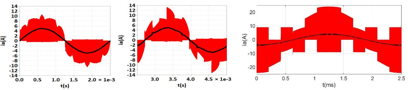
Fig. 2. Phase A current for 1.2 kW, 400 V Vdc, 115 V Vacrms for
(a) unity power factor (b) 30° lagging & (c) 90° lagging


