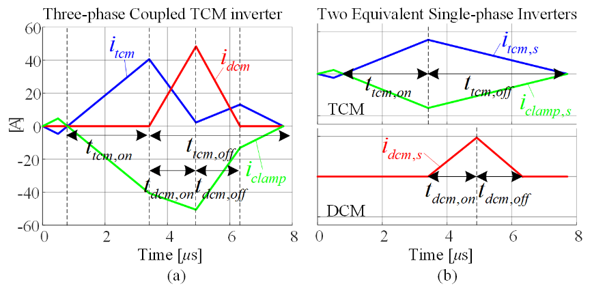
Fig. 1. Decomposition of current waveforms. (a) By three-phase TCM inverter. (b) By two equivalent single-phase inverters
To improve the power-density of ac-dc converters, zero-voltage switching (ZVS) schemes have been widely investigated. Triangular conduction-mode (TCM) delays turn-off time to gener-ate reverse current. The reverse current discharges the junction capacitance before a MOSFET turns on, thus achieving ZVS. This method has been extended to three-phase applications by operating the other two phases with two different conduction-modes: discontinuous conduction-mode (DCM) and clamped, similar to a discontinuous pulse-width modulation (DPWM) scheme. The variation of the switching frequency is narrow, while the switching frequency can go up to hundreds of kHz with an efficiency near 99 %. However, the presence of three-phase coupling, and transitions of the conduction-modes along the line-cycle, introduce complexity in the modeling and control. While one phase is clamped to negative or positive dc-rail, the other two phases operate as two dc-dc buck con-verters in TCM and DCM within a switching period. The principle of TCM and DCM highly de-pends on the current slope, and through three-phase coupling, the operation of one phase af-fects the slope and trajectory of the other phases current. This complicates the operation. In this paper, a decoupled modeling approach is proposed for three-phase TCM inverters utilizing three different conduction-modes for ZVS operation. If DCM-phase current goes back to zero before the zero-crossing of clamp-phase current, the switching frequency is irrelevant to the operation of DCM phase. It is only determined by TCM phase and clamp phase. Under such a condition, the current waveform can be decomposed into two equivalent single-phase TCM and DCM inverters. The current waveform of the three-phase coupled case, shown in Fig. 1 (a), is a superposition of two single-phase inverter waveforms, shown in Fig. 2 (b). By this simplification, the behavior of the circuit can be easily interpreted, and techniques for a single-phase TCM inverter can be directly applied to the three-phase TCM inverter. The proposed modeling has been verified through Simplis simulation. Analytic solutions of small-signal gains for average current along 30° are compared with the simulation result in Fig. 2, as an example.
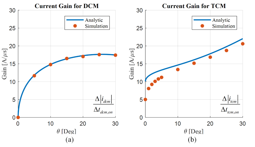
Fig. 2. Comparison of modeling and simulation results: Variation of small signal gain for (a) DCM phase (b) TCM phase.


