


LIBRARY
Design of a Compact, Low Inductance 1200 V, 6.5 m&Omega SiC Half-Bridge Power Module with Flexible PCB Gate Loop Connection
Year: 2020 | Author: Grace Watt | Paper: T1.20
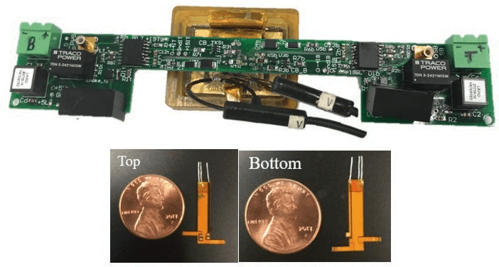
Fig. 1. Gate driver interfaces with flexible PCB and leaves room for Rogwoski coils; size of flexible PCB against a penny; pins for gate, Kelvin, and drain
The design of this power module includes new methods in order to obtain low inductance, compact size, and reliable performance using Wolfspeeds 1,200 V, 13 m&Omega SiC MOSFET. Use of the MOSFET body diodes increases the potential power density by eliminating the need for external antiparallel diodes. Reduction of the gate loop inductance is achieved with a flexible PCB serving as the gate, desaturation point, and Kelvin-source interconnection. Lastly, a balanced/symmetrical DBC layout increases the likelihood of current balance in the commutation loop. The final design is shown in Fig. 1, with the patterned DBC and the die on top, the base plate, and the housing.
One of the more novel and challenging elements of the module fabrication process is attaching the flexible circuit on the bare die due to the small area available for attachment, heat sensitivity of the die, and incompatibility of some attachment materials to the die. The dice use a specialized nickel: gold top coat and additional space between the gate and source pads. The flexible PCB is attached using solder paste.
To test the functionality of the half-bridge SiC power module, a static and dynamic characterization is performed. The static characterization includes output and transfer curves. A clamped inductive load tester allows for dynamic characterization under different load currents. The tester was designed with vias to easily attach to pins coming out of the flexible PCBs (Fig. 1).
New techniques used in the design of this power module take advantage of the properties of SiC. Two power modules are designed to compare current sharing behavior: 1) the control sample with balanced dice, and 2) the other with imbalanced dice. The individual die currents are measured with Rogowski coils (Fig. 2) to determine the effects of the imbalanced die on power module performance.

Fig. 2. Half-bridge power module with Rogowski coil around bottom side wire bonds
