LIBRARY
Small-signal Stability Impact of Utility PV with Reactive Power Control on the Medium Voltage Distributed Systems

A known broad statement is that active power injected by PV inverters increases the system voltage. In what regards the reactive power compensation capability of PV inverters, this paper showed that the reactive power control mode Volt-var droop mode of Q = f (V) is preferred over other reactive power control modes after the static analysis of voltage regulation effect and the impact on grid power loss.
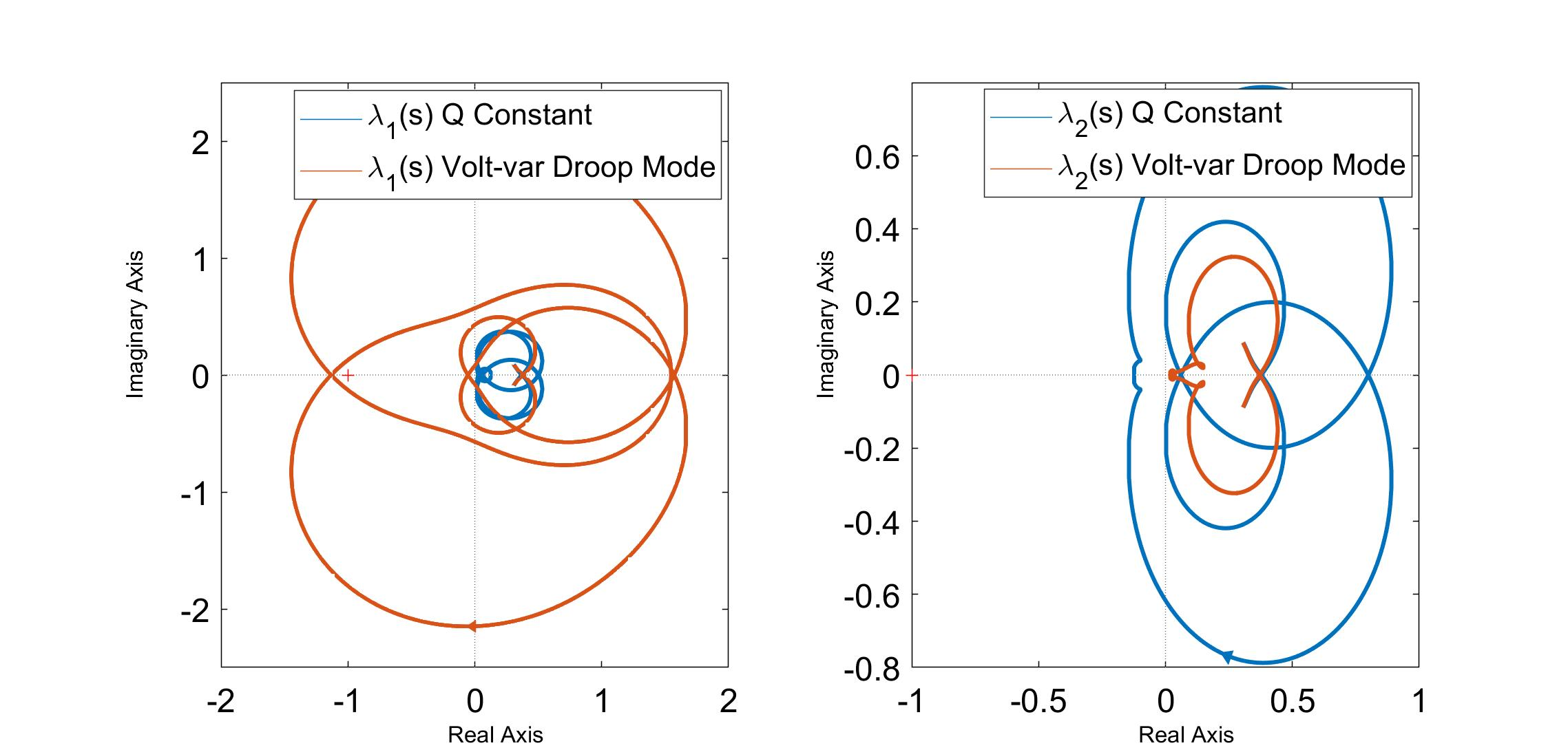
The terminal impedances in DQ frame are derived of utility-scale PV farm based on small signal model of PV inverters as shown in Fig.1. A comparison is done among impedances of PV inverters under 5 different reactive power control modes, based on which GNC is used to assess the grid-PV connection stability as shown in Fig. 2. The volt-var control mode changes PV terminal impedance signs and magnitudes significantly and may cause unstable connection to the grid. The stability assessment is proved by time domain simulation and also eigenvalues acquisition from the state space model of the whole system with PV generators.


