RESEARCH
SiC MOSFET Characterization, Packaging, and Reliability at 300 ðC

The HTRB test stresses the blocking capability of the MOSFET. A high voltage is placed on the drain to source potential of the MOSFET, which results in edge termination breakdown, gate oxide breakdown, and MOSFET drift region breakdown. Precursors for failure during HTRB include a shifted VAV, increased IDLEAK, as well as VTH shift or gate oxide breakdown.
The HTGB test stresses the gate oxide layer of the MOSFET. A high voltage is placed on the gate to source potential of the MOSFET, which results in a drift in the VTH or gate oxide breakdown.
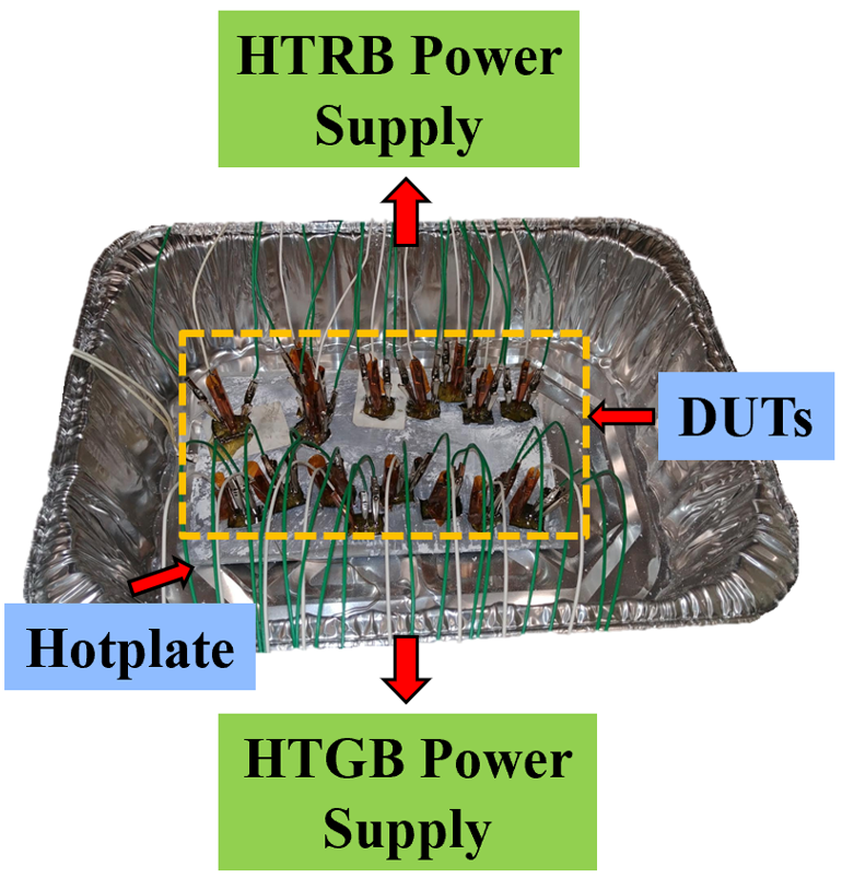
Fig. 1 shows the experimental test setup for the HTGB and HTRB tests. 16 samples (8 for HTRB and 8 for HTGB) are tested. The samples are placed on a hotplate. Device junction temperature is kept at 300 °C. Every 100 hours, the devices are cooled to room temperature and removed from the test fixture. Each device has static characterization performed and is replaced back in the test fixture. The temperature is taken back up to 300 °C. These tests were designed in accordance with standards listed in JEDEC's A108C and Automotive Electronics Council's (AEC) Q101 forms.
Incremental static characterization is performed on the devices during the test. Every 100 hours, the devices are measured on the Agilent B1505A curve tracer. Failure is defined to be any characteristic outside of nominal datasheet values.
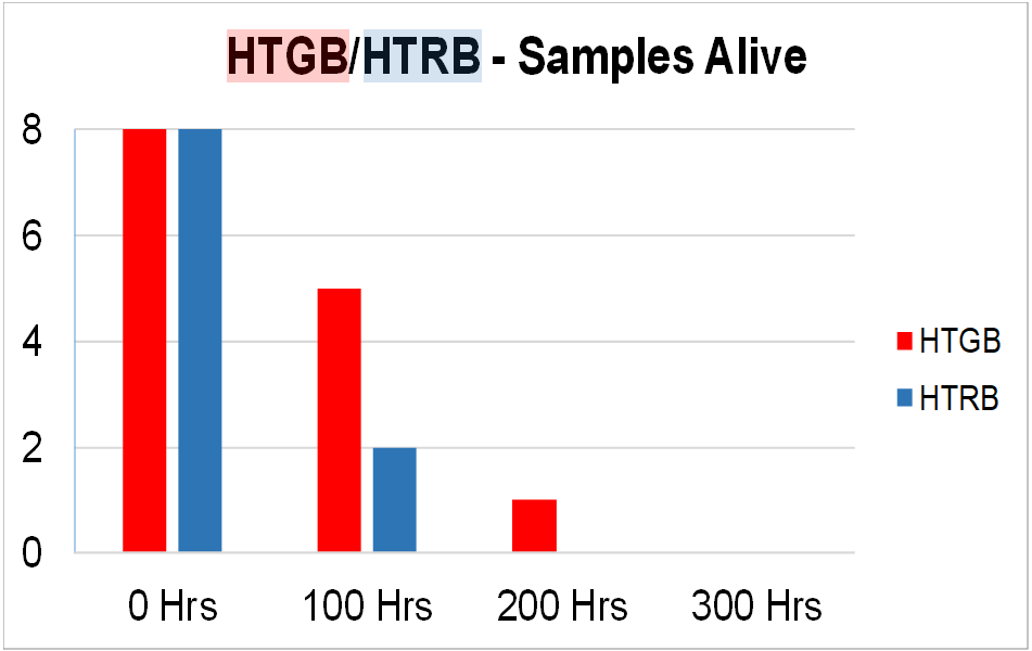
Fig. 2 shows the results from the HTGB and HTRB tests. As shown, all devices failed within 300 hours. For the HTRB test, 6 of the 8 samples catastrophically failed within 100 hours. Catastrophic failure is defined to be a short exhibited across the drain to source or gate to source of the MOSFET. For the HTGB, 2 of the 6 samples failed catastrophically within 100 hours.


